Page 5 of 6 DATA SHEET E85001-0609
Not to be used for installation purposes. Issue 1
Ordering Information
Catalog
Number
Description
Ship Wt.
lbs (kg)
SIGA-CC2A
Dual Input Signal Module (Standard
Mount) with Class A Operation
0.5 (0.23)
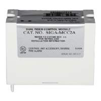
SIGA-MCC2A
Dual Input Signal Module (UIO Mount) with
Class A Operation
0.18
(0.08)
Related Equipment
27193-21 Surface Mount Box - Red, 2-gang 2 (1.2)
27193-26 Surface Mount Box - White, 2-gang 2 (1.2)
SIGA-UIO2R
Universal Input-Output Module Board
w/Riser Inputs - Two Module Positions
0.32
(0.15)
SIGA-UIO6R
Universal Input-Output Module Board
w/Riser Inputs - Six Module Positions
0.62
(0.28)
SIGA-UIO6
Universal Input-Output Module Board
- Six Module Positions
0.56
(0.25)
235196P Bi-polar Transient Protector
0.01
(0.05)
Accessories
MFC-A
Multifunction Fire Cabinet - Red, supports
Signature Module Mounting Plates
7.0 (3.1)
SIGA-MP1
Signature Module Mounting Plate, 1
footprint
1.5 (0.70)
SIGA-MP2
Signature Module Mounting Plate,
1/2 footprint
0.5 (0.23)
SIGA-MP2L
Signature Module Mounting Plate,
1/2 extended footprint
1.02
(0.46)
Specifications
SIGA-CC2A SIGA-MCC2A
Voltage 20 VDC
Current
Standby: 310 µA
Alarm: 135 µA
Ground fault
impedance
10 k Ohms
Wire Size
12 to 18 AWG
(2.5 to 0.75 sq mm)
Maximum line
impedance
Refer to the installation manual for
your fire alarm control panel
Output rat-
ings (special
applications)
24 VDC: 2 A
25 VAC audio: 50 W
70 VAC audio: 35 W
EOL resistor value: 47 kΩ
Max. circuit resistance: Refer to manual
Max. circuit capacitance: 0.1 µF
Operating
environment
Temperature: 32 to 120°F (0 to 49°C)
Humidity: 0 to 93% RH, noncondensing at 90°F (32°C)
Storage
temperature
-4 to 140°F (-20 to 60°F)
Mounting
North American 2-1/2 in.
deep 2-gang box
Standard 4 in. square box
by 1-1/2 in. deep box
European 100 mm square
box
UIO2R or UIO6(R)
motherboard
Synchroniza-
tion
Meets UL1971 synchronization requirement. All signal-
ing devices signal within 0.01 seconds of each other for
a period of at least two hours while maintaining a one
hertz signal rate. (For a list of compatible devices, see
“Compatibility”).
Note: For synchronization, the maximum resistance
between any two devices is 20 Ω. See the voltage
specifications for the MCC2A, the signaling device, and
the control panel to determine the maximum allowable
wire resistance.
Strobe Capacity
Strobe candela rating Maximum strobes
15, 15PS, 5A 29
30, 15/75, 3A, 7A 16
60, 75PS, 6A 11
75 10
110, 8A 8