Functional description
Page 16 of 72 MSM-USM2G-BA-UK-004
3.8 Labelling
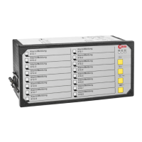
Fig. 3.6: Insertion of labelling strips after
removing the front frame
3.9 Monitoring LEDs, buttons and connections
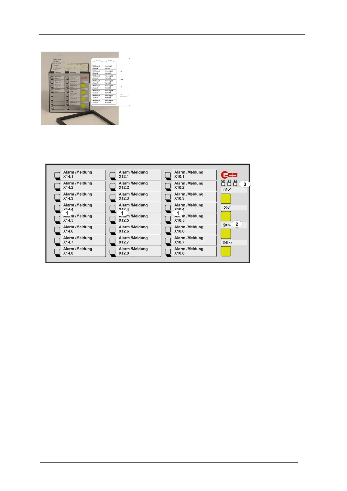
Fig. 3.7: Front view of the USM24
[1] Alarm LEDs (function depending on reporting sequence)
[2] Buttons 1 … 4, (function depending on reporting sequence and parameterization)
[3] Monitoring LEDs
OK - Watchdog LED „Self-monitoring“
Steady light green - No error, no alternative operating state
Off - No supply voltage or device defective
Flashing red - Error ( section „Diagnostic functions“)
Flashing green - Signaling of an alternative operating state
(see table below)
S1 – Watchdog LED supply voltage 1
Off - No supply voltage 1 and 2
Steady light red - Error supply voltage 1
Steady light green - Supply voltage 1 error free
S2 – Watchdog LED supply voltage 2 (redundant supply)
Off - Option redundant supply voltage not integrated
Steady light red - Error supply voltage 2
Steady light green - Supply voltage 2 error free
Labelling of the annunciators is done by means of
designation strips that can be inserted beneath
the cover foil after removing the front frame.
The designation strips with signal names can be
created and printed directly from the
parameterization interface on the web-server or
generated manually from labelling strips in Word-
format.