Functional description
Page 18 of 72 MSM-USM2G-BA-UK-004
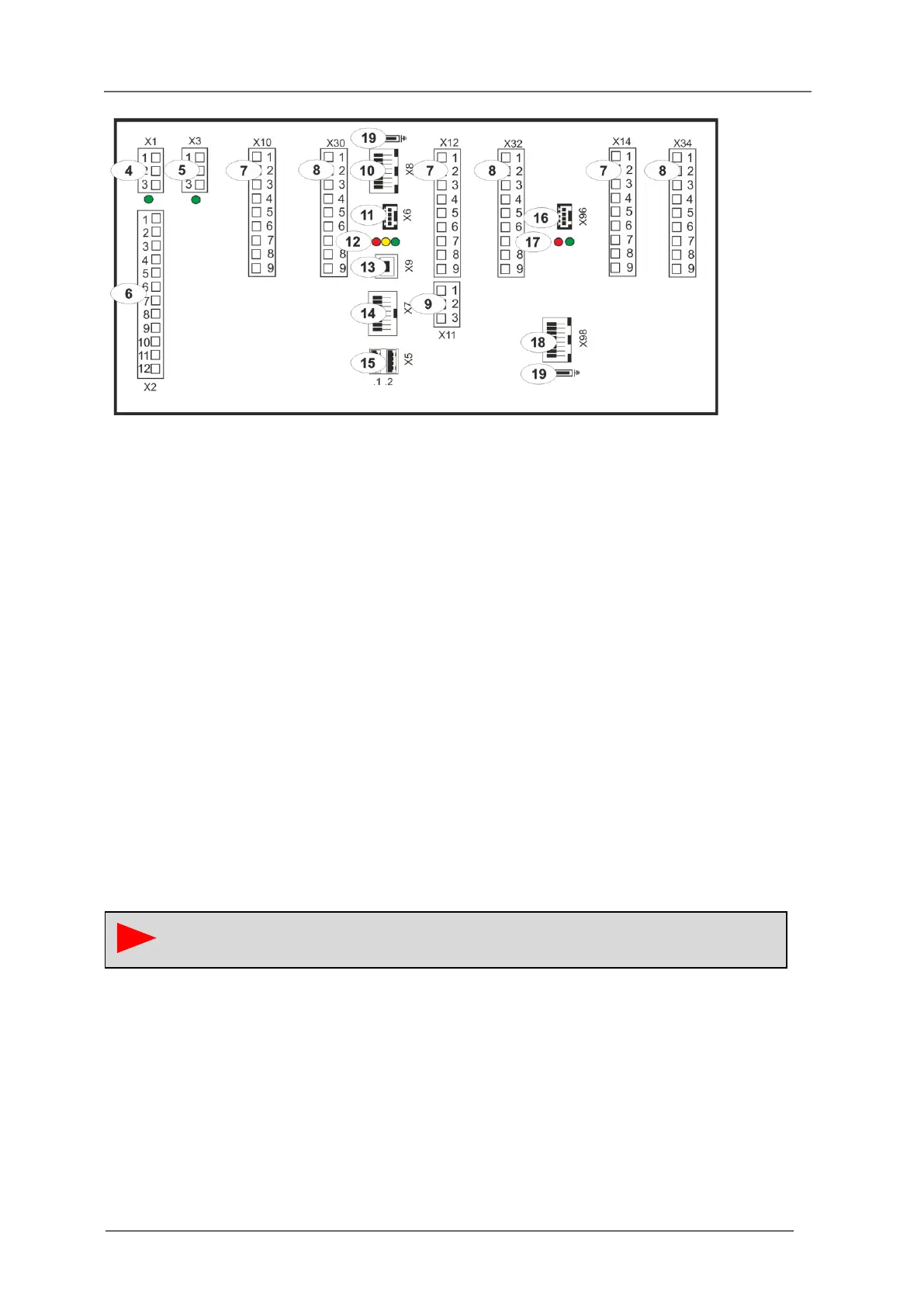
Fig. 3.8: Back view of the USM24
[4] Terminals supply voltage 1 (green LED indicates present voltage)
[5] Terminals supply voltage 2 (redundant supply voltage optional)
(green LED shows present voltage)
[6] Terminals function relays 1 - 4
[7] Terminals alarm inputs
[8] Terminals additional cards (optional)
[9] Terminals function inputs 1 and 2
[10] LAN connection (Ethernet / RJ45)
[11] Terminals serial interface (RS232 optional RS 485)
[12] Watchdog LEDs „Communication“
red - Tx serial interface
green - Rx serial interface
yellow - Can-Bus
[13] Service- and diagnosis interface USB-B (factory interface)
[14] CAN-Bus interface (Systembus / RJ45)
[15] 2 x USB-A interface
[16] Terminals serial interface (RS232 optional)
[17] Watchdog LEDs „Communication“ (optional)
red - Tx serial interface
green - Rx serial interface
[18] LAN connection (Ethernet / RJ45, optional)
[19] Connection for ground potential
On the USM 08, terminal X11 (function inputs) is not located under terminal X12, but
under terminal X10.