6
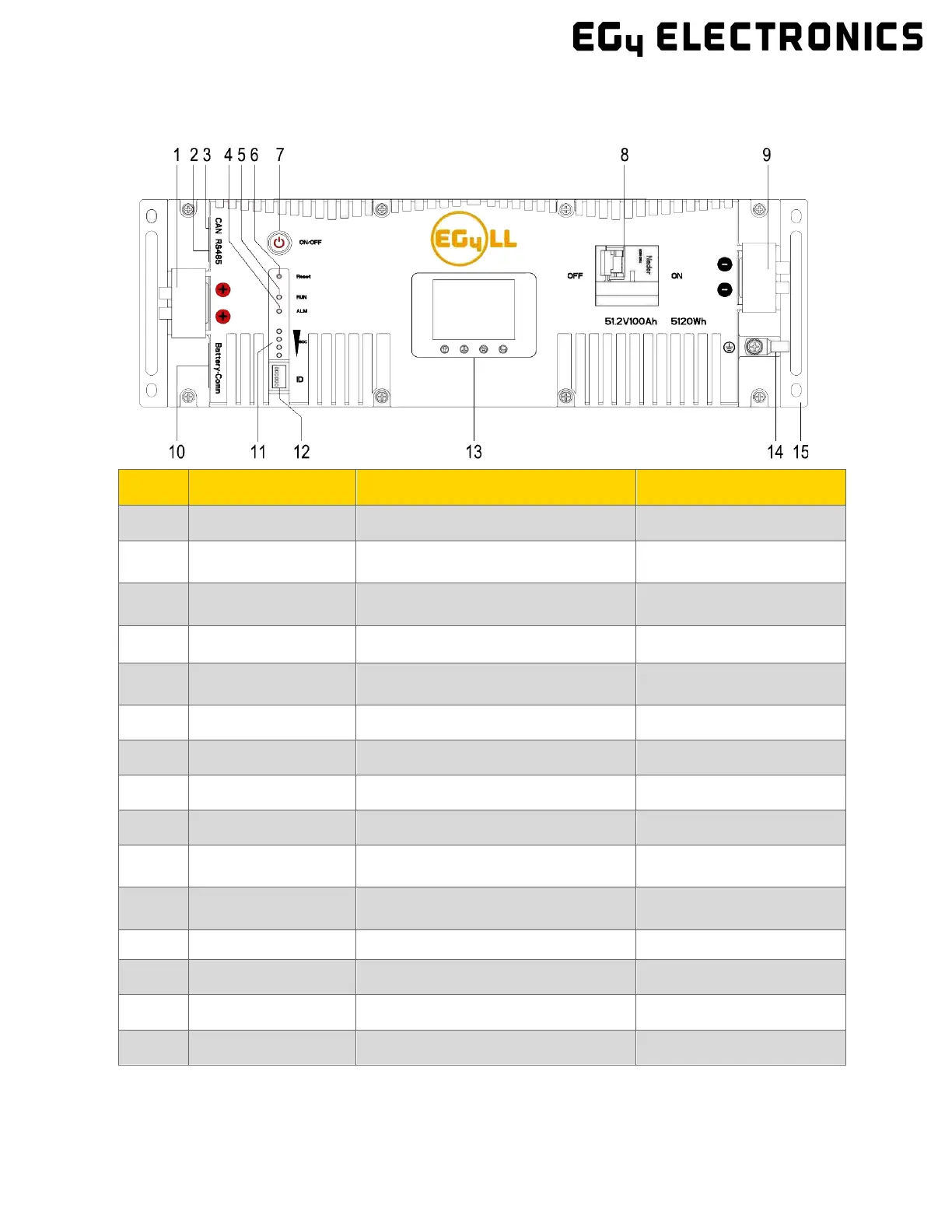
3.2.1 Battery Diagram
No. Item Description Remarks
1
Positive terminal M6 bolt (x2)
2
RS485 port RS485 communication interface
Pin 1 & Pin 8 ‒ RS485_B
Pin 2 & Pin 7 – RS485_A
3
CAN port CAN communication interface
Pin 4 – CAN_H
Pin 5 – CAN_L
4
ALM LED Alarm status LED
5
RUN LED Operation status LED
Always on if system is
running
6
Reset button Emergency reset
7
ON/OFF button Turns BMS on/off
8
Circuit breaker Shuts down power supply
9
Negative terminal M6 bolt (x2)
10
Parallel battery communication
port
Pin 1 & Pin 8 ‒ RS485_B
Pin 2 & Pin 7 – RS485_A
11
SOC LED State of charge LED
4 green lights = full
charge
ID Board DIP switch board for BMS May be 4 or 6 DIP
13
LCD Display Shows battery information
14
Ground screw Provides safe route for grounding
15
Handle For carrying/handling battery
 Loading...