GB
- 28 -
6. Assembly
Danger! Pull out the power plug before carry-
ing out any maintenance, resetting or assem-
bly work on the circular saw!
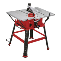
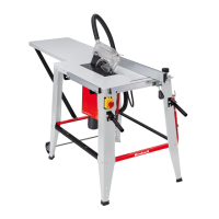
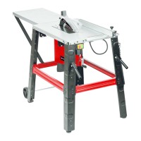
6.1 Assembling the base frame (Fig. 3-4)
Danger! Make allowance for the weight of the
machine and arrange another person to help you
if necessary!
•
Turn the bench-type circular over and set the
saw down on the floor or on some other work
surface. Important! Place suitable material
(e.g. packaging material) between the table
surface and the surface on which it is stood to
prevent any damage to the table surface.
•
Important! Only fasten all the screw connec-
tions between the base frame and machine
loosely at first. Wait until you have returned
the bench-type circular saw to its working po-
sition before tightening the screw connections
securely. This is so that you can be sure the
base frame is aligned level with the surface
on which it is stood.
•
Use the hexagon screws (46) and washers
(47) to fasten the four legs (29) loosely to the
saw.
•
Then use the lock bolt (48), washer (49),
spring washer (50) and nut (51) to screw the
cross-struts loosely to the legs. Make sure
that the tongue-and-groove connection bet-
ween the cross-strut (30) and leg (29) enga-
ges properly.
•
Plug the rubber feet (13) onto the legs (29).
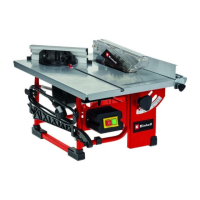
6.2 Assembling the table width extension
(Fig. 5, 6)
•
Use the screws (54), washers (49) and nuts
(51) to fasten the table width extensions (33)
and (34) loosely to the saw table (1).
•
Remove the screws (46) from the base frame
(52) on the left and right-hand side to enable
the struts (31, 32) and the base frame to be
fitted.
•
Important! The struts for the left and right-
hand sides are different in length. You there-
fore have to fit the long struts (31) on the left-
hand side of the saw table (1) and the short
struts (32) on the right-hand side.
•
Fasten the struts (31, 32) loosely to the base
frame (52) with screws (46), but do not tigh-
ten.
•
Use the screws (54), washers (49) and nuts
(51) to screw the struts (31, 32) loosely to the
table width extensions (33, 34).
•
Align the table width extensions (33, 34) level
with the saw table (1).
•
Then tighten the screw connections referred
to in 6.2. Use both the wrenches (38) and (39)
to do this.
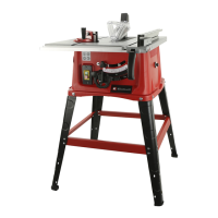
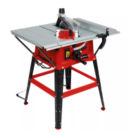
6.3 Standing the bench-type circular saw up-
right (2, 7-9)
•
Turn the machine over so that it stands on its
legs.
•
The bench-type circular saw must be stood
on a flat surface.
•
Then tighten all loose screw connections. Use
both the wrenches (38) and (39) to do this.
•
Screw the additional legs (37 to the rear legs
(29) so that they point towards the rear of the
machine. Us the screws (54), washers (49)
and nuts (51) to fasten them.
•
Warning! Don not fit the additional legs (37)
too far away from the surface on which the
machine stands; they are intended to provide
protection against tipping over.
•
Remove the screw (53) from the shaft (25).
•
Slide the hand wheel (8) and then the crank
(10) onto the shaft (25) as shown in Fig. 9.
•
Important! The shaft (25) and the crank (10)
engage with a positive fit, i.e. the flat surface
on the shaft (25) and the flat surface in the
hub of the crank (10) must lie on top of each
other to enable the crank (10) to be slid on.
•
Secure the hand wheel (8) and crank (10)
with the screw (53).
6.4 Changing the table insert (Figure 12)
•
To prevent increased likelihood of injury, the
table insert should be changed whenever it is
worn or damaged.
•
Remove the countersunk head screws (17).
•
Remove the worn table insert (6) by pulling it
out through the opening at the back past the
splitter (5) and the saw blade (4).
•
Fit the replacement table insert by following
the above in reverse.
6.5 Fitting / removing the splitter together
with the saw blade guard (Fig. 10 - 13)
•
Remove the table insert (6) by undoing the
countersunk head screws (17) (see 6.4).
•
Using the crank (10) set the saw blade (4) to
the maximum cutting depth.
•
Slacken the fastening screw (19) until the
gap between the fastening plate (40) and the
support surface opposite is approx. 5 mm.
Caution! Do not completely undo the faste-
Anl_TC_TS_254_U_SPK9.indb 28Anl_TC_TS_254_U_SPK9.indb 28 29.10.2019 10:51:2629.10.2019 10:51:26