Electronic convection oven rev. 11 ________________MODD. EKF 616 TC – EKF 664 TC – EKF 711 TC – EKF 1016 TC
EKF 1064 TC – EKF 1111 TC – EKF 1664 TC – EKF 2011 TC
_________________________________________________________________________________________ page 11
3.8 Power supply cable connection
(Modd. EKF 616 TC – EKF 664 TC – EKF 711 TC – EKF 1064 TC –EKF 1064 TC – EKF 1111 TC )
Remove the back and left side of the appliance to access the power supply terminal board.
Loosen the cable retainer at the rear (bottom) of the appliance (see Fig.1) and run the cable
through it until reaching the terminal board. Prepare conductors for connection with the terminal
board so that the earth conductor is the last to be extracted from its terminal in the event the
cable should be abnormally pulled.
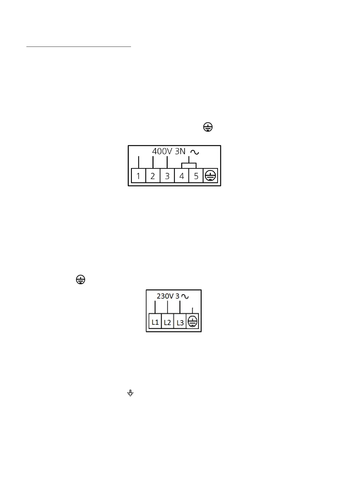
Connect the 3 phase conductors (L1, L2, L3) of the cable to the terminals marked with
“1”(brown conductor) “2”(black conductor) and “3”(grey conductor) of the terminal board, the
neutral conductor (blue) to the terminal marked with “4” or “5” and the earth conductor
(yellow/green) to the terminal marked with the symbol (see diagram also available by the
terminal board):
(Mod. EKF 1064 TC/0/029 - EKF 1111 TC/1/029)
Remove the back and left side of the appliance to access the power supply terminal board.
Loosen the cable retainer at the rear (bottom) of the appliance (see Fig.1) and run the cable
through it until reaching the terminal board. Prepare conductors for connection with the terminal
board so that the earth conductor is the last to be extracted from its terminal in the event the
cable should be abnormally pulled.
Connect the 3 phase conductors (L1, L2, L3) of the cable to the terminals marked with “L1” “L2”
and “L3” of the terminal board, and the earth conductor (yellow/green) to the terminal marked
with the symbol (see diagram also available by the terminal board):
Tighten the cable retainer on the rear of the appliance; fit the left side and back on again. The
cable must be as per specifications in the "Technical features" table (paragraph 2.2). The
appliance must be connected to an equipotential system the effectiveness of which must be
suitably assessed according to applicable regulations.
This connection must be performed between different appliances through the suitable terminal
which is marked with the symbol . The equipotential conductor must have minimum section 2.5mm². The
equipotential terminal is at the rear of the appliance.