EQUIPMENT DESCRIPTION
NP-DK50 DE-18_02-2019 9
2. EQUIPMENT DESCRIPTION
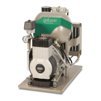
1. Switch, main connector, fuses
2. Hour counter
3. OUT – compressed air output
4. Outlet pressure gauge (accuracy ± 5%)
5. WALL – input of compressed air from central distribution (Auxiliary
equipment)
6. Suction filter
7. Equipotential (ground) pin
8. Condensate tank
9. Power indicator
10. Socket for the electrical cord
11. Compressor
12. Safety valve
13. Air tank
14. Filter (40 μm) and water trap
15. Pressure regulator
16. Filter (5 μm) and water trap
17. Control electronics
18. Suction filter
19. Cooler
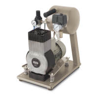
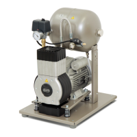
The compressor contains an oil-free piston (11) driven by a low-maintenance single-phase
electric motor. Compressed air is cooled in the cooler (19) where condensed water is
separated into a separate tank (8). Incoming air passes through two filters (6,18)
undergoing double filtration as it passes through the system (14,16). Constant pressure at
the output is maintained by the pressure regulator (15). The built-in air tank (13) enables
peak air consumption of 200 L/min.
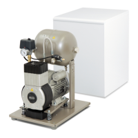
The following applies to products with additional equipment – WALL coupling (5):
If the device is equipped with a WALL quick coupling (5), it can be used as a back-up air
source. In this configuration, the respiratory equipment is supplied with compressed air
from the central air distribution of the medical facility. Air pressure in the central distribution
line is sensed by a pressure sensor. If the pressure is sufficient, the compressor stays in
STANDBY mode. If the pressure falls, the control unit automatically places the compressor
into operation.
When the compressor is used as the main source of air, the control unit determines its
operation based on current demand for air. If air consumption is zero, the device switches
to STANDBY mode.