9
The pressurisation unit is supplied
with a flying lead for the Mains Power
Connection; this cable should not
be replaced.
Mains connection must be via a
fused isolator rated at 13 Amps and
positioned locally to the unit. and
within 1 metre of the unit. The cable
size serving the unit shall be sized
in accordance with the IEE
Electrical Regulation.
After the outer casing has been
removed, the Electrical Terminal
Connection rail can be located
on the front-hinged inner door.
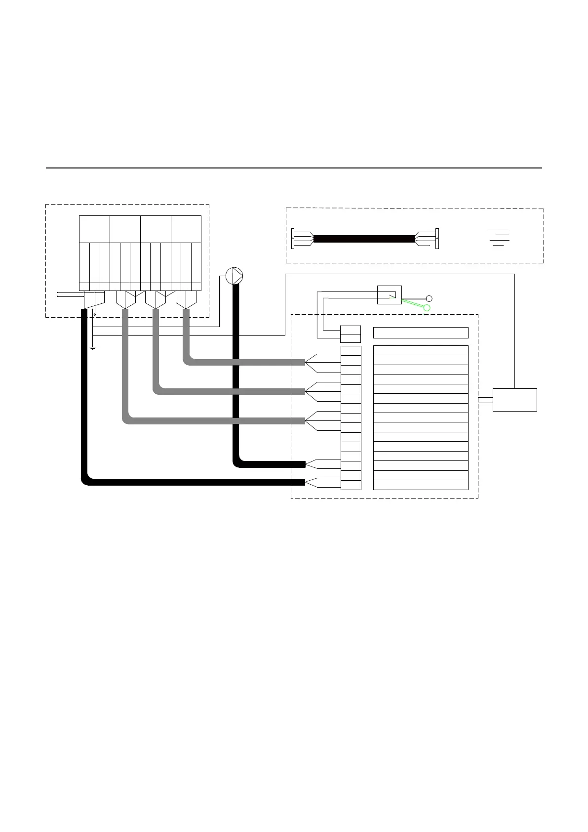
See Fig 9.1 for connection details.
9.1 Wiring details
The High & Low alarm switches have
been wired to allow volt free indication
of faults. If the power interruption of
the associated Boiler/Chiller plant is
required, the 230V 50Hz power supply
for the associated Boiler / Chiller plant
should be connected as follows:
Interlock circuit In Term 2
Link wire Terms 3 & 5
Interlock circuit Out Term 6
If a general alarm is required Link
Terminal 6 to Terminal 8. Then the
Interlock Circuit Out is Terminal 9.
In this manner, if one of the alarm
switches are activated, the power
supply to the associated Boiler /Chiller
plant will be interrupted.
9.0 Electrical Connection
Electrical Connection
Figure 9.1 – wiring diagram
MAINS SUPPLY
240V/50HZ
10AMPS
GENERAL
FAULT ALARM
VOLT FREE
(MAX 240V 0.5A)
HIGH
PRESSURE
ALARM VOLT
FREE(MAX 240V
0.5A)
LOW PRESSURE
ALARM VOLT
FREE (MAX 240V
0.5A)
1
2
3
4
5
6
7
8
9
10
11
12
EARTH
NEUTRAL
LIVE
NORMALLY OPEN
NORMALLY CLOSED
COMMON
COMMON
LOW ALARM NO (PU POWERED)
LOW ALARM NC (PU POWERED)
LOW ALARM COMMON
HIGH ALARM NC (PU POWERED)
HIGH ALARM NO (PU POWERED)
HIGH ALARM COMMON
GENERAL ALARM NO (PU POWERED)
GENERAL ALARM NC (PU POWERED)
GENERAL ALARM COMMON
PUMP 1 LIVE
PUMP 1 NEUTRAL
MAINS NEUTRAL
MAINS LIVE
GREY
BLACK
BROWN
BROWN
BROWN
BLUE
BLUE
GREY
GREY
GREY
BROWN
BROWN
BROWN
BROWN
BLACK
BLACK
BLACK
BLUE
G/Y
YELLOW
BLUE
GREEN
RED
RED
YELLOW
BLUE
GREEN
PRESSURE TRANSPONDER CABLE
TANK LEVEL SWITCH
MAIN CONTROLLER PCB
USER TERMINAL
240/50Hz
SENSOR
CONNECTOR
BOX
CONNECTOR
RED TERMINAL
YELLOW TERMINAL
BLUE TERMINAL
GREEN TERMINAL
1
4
Not Connected
2
3
4
5
6
7
8
9
10
11
12
13
14
15
1
2
WATER LEVEL SWITCH
BLACK
GREY
BROWN
GREY
BLACK
BROWN
PUMP
NORMALLY CLOSED
NORMALLY OPEN
NORMALLY CLOSED
COMMON
NORMALLY OPEN
DISPLAY PCB