1360 Page 12
Electro-Mech Scoreboard Co. • 120 Industrial Parkway • Wrightsville, GA 31096
Phone: (800) 445-7846 • Fax (478) 864-0212 • Email: score@electro-mech.com
Power Connections
The scoreboard requires 120 VAC service at the scoreboard to operate properly.
Maximum power consumption of Model 1360: 155 Watts. Make sure that power
cable is rated for this electrical load. Install the power cable in conduit. Avoid running
the power cable in close proximity to the control cable. The following steps describe how
to connect the scoreboard to the power source:
1. Feed the power cables through one of the holes in the plate below the access panel.
2. Crimp fork terminals to the power cable wires.
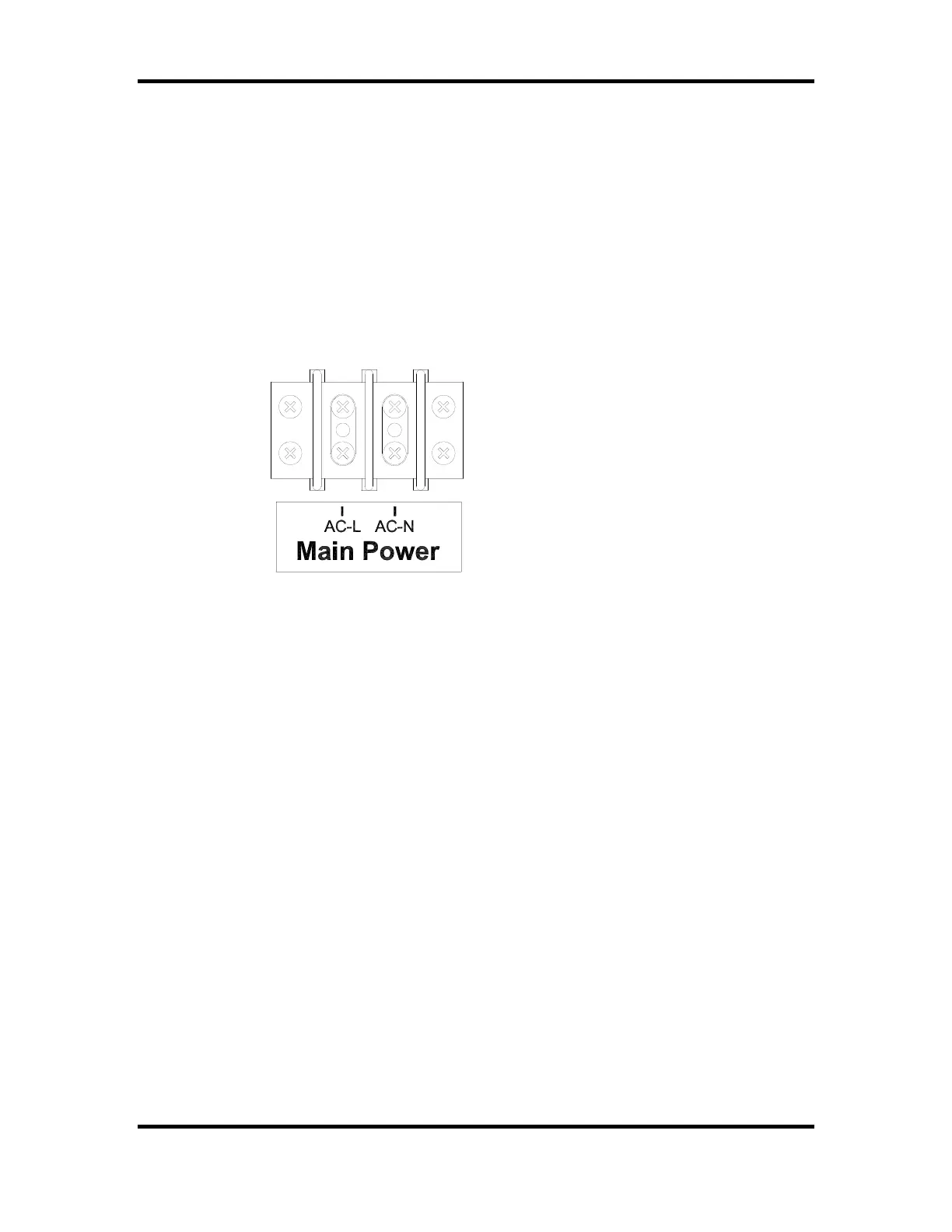
3. Connect the power cable wires to Main Power terminal block on the junction chassis
according to figure 8.
Figure 8 Power Connections
Install a power disconnect that isolates all current carrying conductors on one of the posts
below the scoreboard (not the ground conductor). If a secondary switch is installed near
the scorekeeper’s table, it should also isolate these conductors. Place the power
disconnect in the OFF position between games to help protect the scoreboard from
lightning damage. A power disconnect on the scoreboard post also provides a convenient
way of turning the scoreboard off during maintenance or repairs.
Horn Installation
The items provided to install the horn are the horn, the mounting bolt, and the mounting
bracket. Items which are not provided but are necessary for proper installation are ¾”
conduit, two ¾” male conduit connectors, a ¾” straight male conduit connector, two
wires, two forked crimp terminals, and two butt splice connectors. The electrical
requirements for the horn are 0.35 A 120 VAC. The horn is mounted to the top of the
scoreboard. If a horn was purchased with the scoreboard, a tapped hole is provided to
fasten the horn to the scoreboard. The mounting bolt is screwed into the tapped hole at
the factory. The following steps describe the assembly and mounting of the horn:
1. Cut a piece of ¾” conduit of sufficient length to reach from the horn mounting point
to one of holes in the plate below the access panel.
2. Attach the conduit connectors to the ends of the conduit.
3. Cut two pieces of wire of approximately 4 feet longer than the conduit.
4. Push the wires through the conduit.