1360 Page 13
Electro-Mech Scoreboard Co. • 120 Industrial Parkway • Wrightsville, GA 31096
Phone: (800) 445-7846 • Fax (478) 864-0212 • Email: score@electro-mech.com
5. Splice the horn wire leads to the two wires that run through the conduit with the butt
splice connectors.
6. Screw the conduit connector into the threaded hole on the weatherproof back box.
7. Fasten the horn assembly to the scoreboard using the mounting bolt from the
scoreboard.
8. Crimp forked terminals on the ends of the two wires that protrude out of the other end
of the conduit.
9. Pass the wires through one of holes in the plate below the access panel.
10. Fasten the conduit connector to the plate and connect the wires to the Horn terminal
block on the junction chassis. Connect the AC-L wire to the left terminal and the AC-
N wire to the right terminal.
SL-230 / 330
The SL-230 / 330 RF MODEM SYSTEM is designed to eliminate the control cable
between the scoreboard and the control console on Electro-Mech Scoreboard MM and
MP series scoreboards as well as all LED scoreboards. If you have purchased this
accessory, disregard the section of this manual titled Control Cable Installation. Refer
to the installation manual provided for this product.
Control Cable Installation
The control cable connects the scoreboard to the control console. Install the control cable
in conduit. If the cable is ever damaged, it is easier and less expensive to replace a cable
in conduit. A small junction box with a ¼” stereo jack mounted on the face plate is
attached to the control cable at the point of operation of the scoreboard. This junction
box should be securely mounted in a clean, dry area within ten feet of the rear of the
control console. Most customers order the control cable with the junction box attached.
Some customers prefer to attach the junction box after the cable is installed. Those
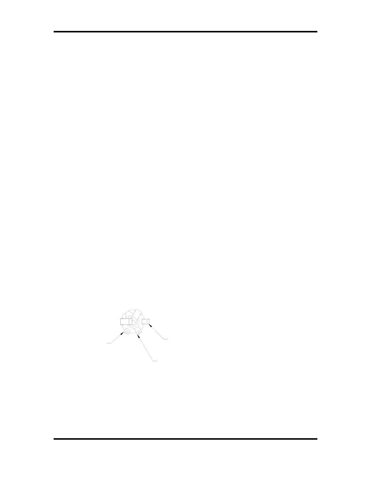
customers must solder the control cable to the ¼” stereo jack. Figure 9 shows the control
cable wire connection points on the rear of the ¼” stereo jack.
2
3
1
PIN 2 - RED WIRE
PIN 1 - BLACK WIRE
PIN 3 - SHIELD WIRE