1360 Page 14
Electro-Mech Scoreboard Co. • 120 Industrial Parkway • Wrightsville, GA 31096
Phone: (800) 445-7846 • Fax (478) 864-0212 • Email: score@electro-mech.com
Figure 9 ¼” Stereo Jack Wiring Diagram
The following steps describe how to connect the control cable to the scoreboard:
1. At the rear of the scoreboard feed the control cable through the left hole in the plate
below the access panel.
2. Crimp fork terminals to the control cable wires and the shield.
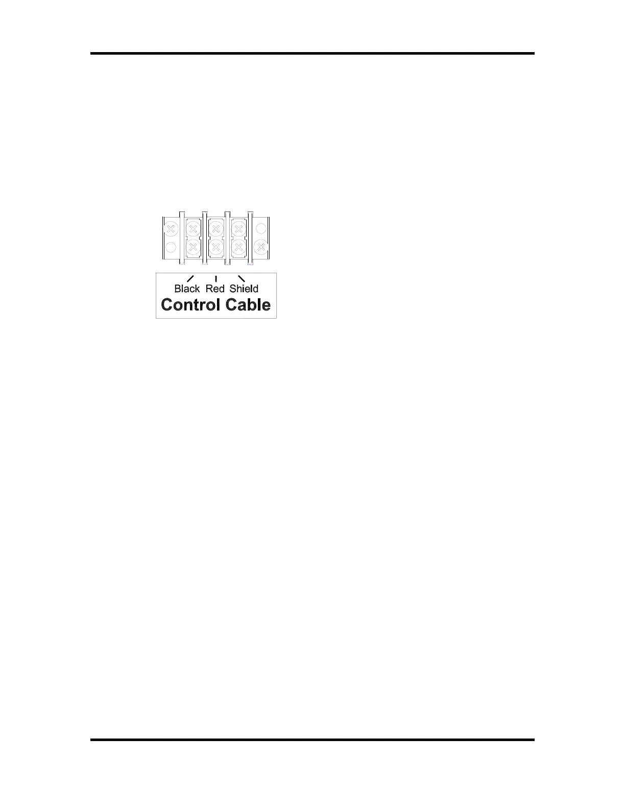
3. Connect the control cable to Control Cable terminal block on the junction chassis
according to figure 10.
Figure 10 Control Cable Wiring Diagram
4. Reinstall the access panel.
Control Console Connections
The 10 ft. extension cable has two molded ¼” stereo plugs attached to it. It is used to
connect the control console to the junction box. The following steps describe how to
connect the control console:
1. Plug one end of the extension cable into ¼” stereo jack on the junction box.
2. Plug the other end into the ¼” stereo jack mounted on the control console back plate.
3. Plug the control console power cord into a grounded NEMA 5-15R 120 VAC
receptacle.
Control Console Safety Warning
This product is equipped with a 3-wire grounding type plug, a plug having a third
(grounding) pin. This plug will only fit into a grounding-type power outlet. This is a
safety feature. If you are unable to insert the plug into the outlet, contact a qualified
electrician to replace your obsolete outlet. Do not defeat the purpose of the grounding-
type plug.