1360 Page 8
Electro-Mech Scoreboard Co. • 120 Industrial Parkway • Wrightsville, GA 31096
Phone: (800) 445-7846 • Fax (478) 864-0212 • Email: score@electro-mech.com
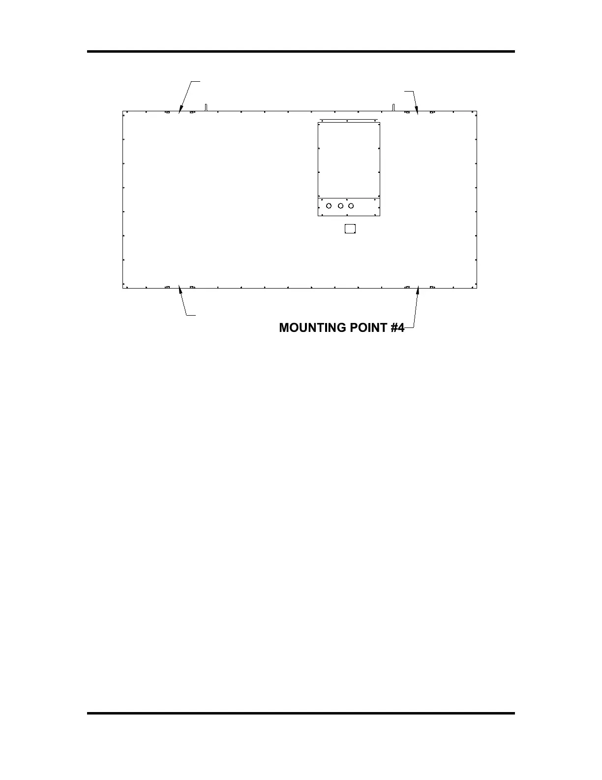
MOUNTING POINT #1
MOUNTING POINT #2
MOUNTING POINT #3
No. of lampholders 107
Replace with 15 W lamp, maximum
Electric shock hazard: Disconnect
and local codes before installation
power before servicing equipment
CAUTION
Check with the applicable state
#3 Industrial Parkway P.O. Box 102
ELECTRO-MECH SCOREBOARD CO.
120 VAC 60 Hz 13.3 A
Date of Mfg.
Serial No. AB-
Model No. MM-1000
Wrightsville, GA 31096-0102
Figure 4 Mounting Points
MOUNTING HARDWARE
Four sets of mounting hardware are provided to attach the scoreboard at these points.
Additional hardware sets are provided to attach the optional top sponsor panels, if
ordered. A single set of mounting hardware for the scoreboard consists of a steel angle
bracket, two threaded rods, two washers, and two nuts. Figure 5 shows an overhead cross
section view and a side cross section view of the scoreboard attached to a post at a
mounting point. A steel bar is riveted inside the scoreboard’s aluminum extrusion frame.
The bar has two tapped holes. The threaded rods screw into these tapped holes. The
washers and nuts are used to clamp the steel angle bracket against the steel post and hold
the scoreboard in place.