Page 41
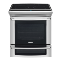
1. Before drawer removal, be sure to turn OFF
the lower oven and let the drawer area cool
completely.
2. Open the drawer to the fully open position.
Using a phillips-head screwdriver remove the two
drawer screws from the insides of the front oven
drawer compartment (See Fig. 1).
3. With one hand hold the drawer front in place.
Use your other hand to pull the glide away from
the oven (See Fig. 2) until the glide hook
disengages (See Fig. 3 & Fig. 4).
4. Repeat from step 3 above for the other side of
the drawer.
5. With both glide hooks disengaged, carefully
lift the drawer up and away from the oven. Push
both drawer glides into lower oven cavity.
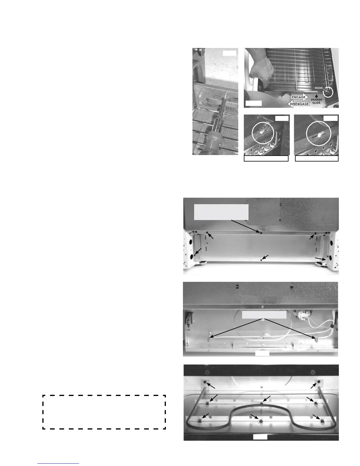
LOWER OVEN COMPONENT SERVICE
From the rear of the range remove the six screws
that secure the lower rear shield. ( Fig. 5 )
Note that the center screw in the upper edge of
the panel is concealed behind the power cord. It
may be necessary to remove the cord to access
this screw.
This screw concealed
by power cord
Fig. 5
Fig. 6
After the shield is removed the wire terminals to
the lower oven element and light can be accessed.
( Fig. 6 )
With the drawer removed and the element wire
harness disconnected remove the eight screws
that secure the element to the base and remove
the element by pulling forward. ( Fig. 7 )
To remove the mounting screws a short / stubby
¼” nut driver or # 1 square drive screwdriver is
required.
Fig. 7
There are sharp edges on the element
brackets and other areas. Protective cloth-
ing and / or gloves are recommended.
Element Terminals
Glide Hook Disengaged Glide Hook Engaged
Fig. 2
Fig. 3
Fig. 4
Fig. 1