Component Teardown and Testing
4-2
Power Transformer Removal
1. Disconnect the power supply cord and then remove
outer case.
2. Open the oven door and block it open.
3. Discharge high voltage capacitor.
4. Disconnect wire leads (primary and high voltage)
from power transformer and the filament leads from
the magnetron and capacitor terminals.
5. Remove four (4) screws holding transformer to
bottom plate.
6. Remove transformer from bottom plate.
Re-install
1. Rest transformer on the bottom plate with its primary
terminals toward the oven face plate.
2. Secure transformer with four screws to bottom plate.
3. Re-connect wire leads (primary and high voltage) to
power transformer and filament leads of transformer
to magnetron and high voltage capacitor. Refer to
“Pictorial diagram” on page 5-1.
4. Re-install outer case and check that oven is
operating Properly.
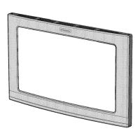
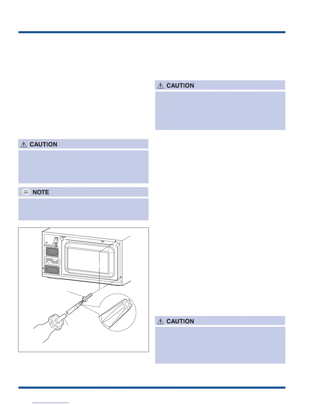
Outer Case Removal
To remove the outer case, proceed as follows;
1. Disconnect the power supply cord.
2. Open the oven door and block it open.
3. Remove the two (2) screws from the lower portion of
the rear cabinet using a T20H Torx type or GTXH20-
100 screwdriver.
4. Remove the remaining two (2) screws from rear and
four (4) screws along the right side of outer case.
5. Slide the entire outer case back out about 1 inch
(3 cm) to free it from retaining clips on the cavity face
plate.
6. Lift entire outer case from the unit.
1. Disconnect oven from power supply before
removing outer case.
2. Discharge the high voltage capacitor before
touching any oven components or wiring.
Special screw
Screwdriver
(Type: TORX T20 H or
GTXH20-100)
Figure 4-1. Outer Case Removal
To discharge the high voltage capacitor, wait for 60
seconds and then short-circuit the connection of
the high-voltage capacitor (that is the connecting
lead of the high-voltage rectifier) against the
chassis with the use of an insulated screwdriver.
When replacing the outer case, the 2 special Torx
screws must be reinstalled in the same locations.
Positive Lock® Connector (No-Case
Type) Removal
1. Disconnect the power supply cord, and then remove
outer case.
2. Open the door and block it open.
3. Discharge high voltage capacitor.
4. Push the lever of positive lock
®
connector.
5. Pull down on the positive lock
®
connector.
To discharge the high voltage capacitor, wait for 60
seconds and then short-circuit the connection of
the high-voltage capacitor (that is the connecting
lead of the high-voltage rectifier) against the
chassis with the use of an insulated screwdriver.