ENV06 EWM11xx EWM21xx EWM25xx/35xx
QUICK GUIDE AND APPLIANCES LIST 43/176 599 72 40-80
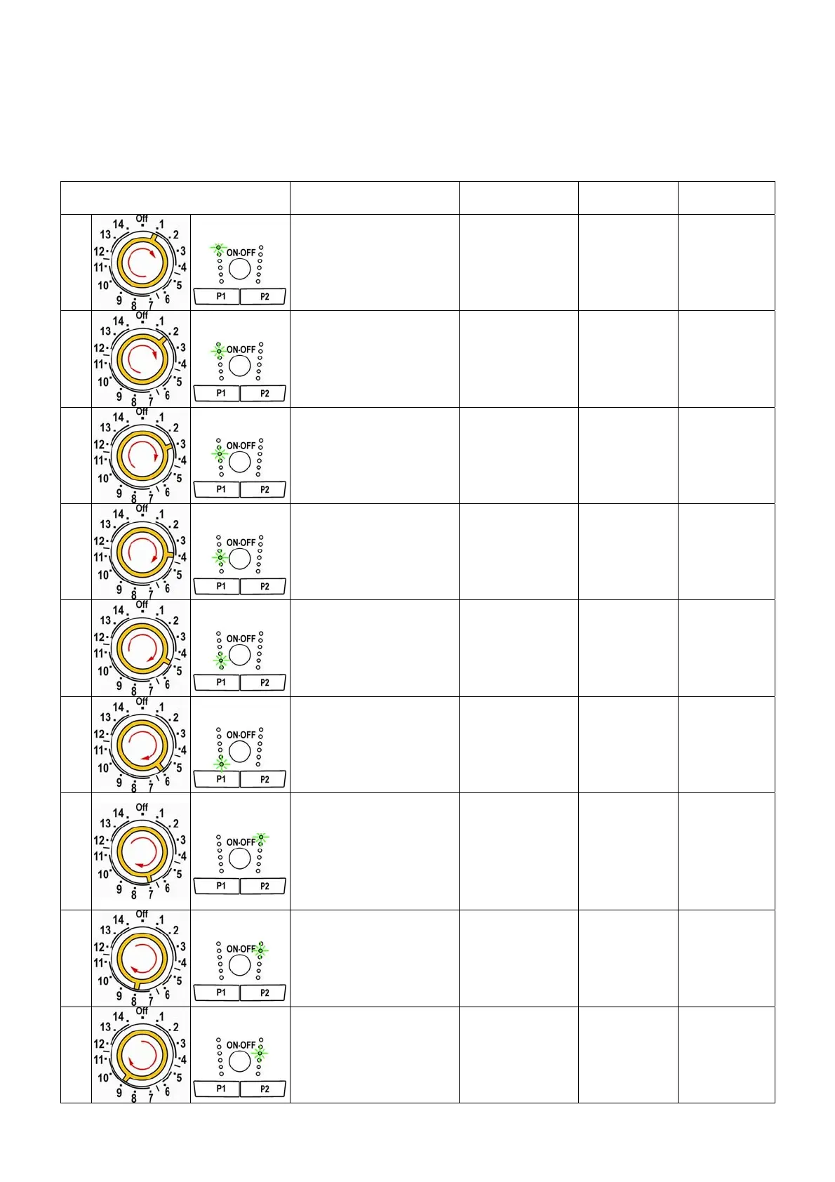
3.3 Phases of the diagnostic cycle
Irrespective of the type of PCB and the configuration of the programme selector it is possible, after entering
diagnostic mode, turning the programme selector clockwise or pushing the buttons P1 or P2 (INPUT
version), to perform diagnostics on the operation of the various components and to read the alarms.
All the alarms are enabled during the diagnostic cycle.
Selector position Components actioned
Operating
conditions
Function
checked
LCD
1
INPUT
- All the LEDs and symbols
light in sequence.
- When a button is pressed,
the corresponding LED or
symbol light.
Always activated
Operation of
the user
interface
All symbols are
activated in
sequence, the
backlight lights
up and then
switches off.
2
INPUT
-
Door interlock
- Wash solenoid
Door locked
Water level below
anti-flooding level
Maximum time 5
minutes
Water ducted
through
washing
compartment
Displays the
water level in
tub
3
INPUT
- Door interlock
- Pre-wash solenoid
Door locked
Water level below
anti-flooding level
Maximum time 5
minutes
Water ducted
through pre-
wash
compartment
(bleach)
Displays the
water level in
tub
4
INPUT
- Door interlock
- Pre-wash and wash
solenoids
Door locked
Water level below
anti-flooding level
Maximum time 5
minutes
Water ducted
through
conditioner
compartment
Displays the
water level in
tub
5
INPUT
- Door interlock
- Bleach/stains solenoids
Door locked
Water level below
anti-flooding level
Maximum time 5
minutes
Water ducted
through
conditioner/stai
ns
compartments
Displays the
water level in
tub
6
INPUT
-
Door interlock
- Wash solenoid if the level
of water in the tub does
not cover the heater
- Heating element
- Recirculation pump
Door locked
Water level above
the heater
Maximum time 10
minutes or up to
90°C (*)
Heating
Recirculation
Wash water
temperature
7
INPUT
- Door interlock
- Wash solenoid if the level
of water in the tub does
not cover the heater
- Motor (55 rpm clockwise,
55 rpm counter-
clockwise, 250 rpm
impulse)
Door locked
Water level above
the heater
Check for leaks
from the tub
Displays the
drum speed
(the real value
divided by ten)
8
INPUT
- Door interlock
- Drain pump
- Motor up to 650 rpm then
at maximum spin speed
(**)
Door locked
Water level lower
than anti-boiling
level for spinning
Drain and spin;
control of
congruence in
closure of level
pressure
switches
Displays the
drum speed
(the real value
divided by ten)
9
INPUT
- Door interlock
- Drain pump
- Motor fan
- Condensation solenoid
valve
- Drying heating element
Door locked
Water level lower
than anti-boiling
level
Drying
Displays the
air temperature