Do you have a question about the Electrolux EWM09311 and is the answer not in the manual?
Explains appliance power saving modes: Stand-By and Stand-Off.
Covers qualified technicians, ESD kit, power, resistance, voltage, heating element, and sharp edges.
Overview of the TC5 model's electronic control system and components.
Details styling, display board, and configuration of the TC5 control panel.
Details the 15-position programme selector knob and its functions.
Lists parameters defining washing programmes like fabric type, temp, and spin.
Configuration and usage of the temperature sensor.
Details the function of option selection sensors.
Explains the START/PAUSE sensor function and its LEDs.
Overview of the TC4 model's electronic control system and components.
Details styling, display board, and configuration of the TC4 control panel.
Configuration and usage of the temperature sensor.
Configuration and usage of the spin speed sensor.
Details the function of option selection sensors.
Explains the Time Manager sensors.
Explains the START/PAUSE sensor function.
Explains door closed indicator and time manager representation.
Explains indicators for wash, rinse, and spin phases.
Summarizes Time Manager levels and icons for different fabric types.
Overview of the TC3 model's electronic control system and components.
Details styling, display, and positioning of LEDs/sensors for the TC3 control panel.
Details positioning of LEDs and buttons on the TC3 display board.
Details the TC3 programme selector and its functions.
Lists parameters defining washing programmes for TC3.
Details functions of buttons, temperature, and spin speed sensors for TC3.
Explains the operation of the ON/OFF button.
Configuration and usage of the temperature sensor for TC3.
Details the function of option selection sensors for TC3.
Explains the Time Manager sensors for TC3.
Explains the START/PAUSE sensor function for TC3.
Describes "Err" message and alarm code display on LCD.
Describes washing calculation and enabling extra rinse option.
Provides a matrix showing compatibility of different wash options.
Explains the function of Rinse Hold and Pre-wash options.
Explains the function of Extra-rinse and No Spin options.
Step-by-step guide to activate DEMO mode for TC5/TC4.
Step-by-step guide to activate DEMO mode for TC3.
Instructions on how to exit the DEMO mode.
Steps to enter diagnostic mode for TC5/TC4.
Steps to enter diagnostic mode for TC3.
Instructions on how to exit the diagnostic mode.
Explains how alarms are indicated on TC5 and TC4/TC3 models.
How alarms are displayed on TC5 models using LEDs.
How alarms are displayed on TC4/TC3 models via screen codes and buzzer.
How to interpret alarm codes on TC5 using START/PAUSE sensor lights.
Provides an example of how alarm codes are displayed.
How alarms behave during diagnostic testing.
Procedure for clearing stored alarms.
Steps to access and view the appliance's operating time.
Explains the sequence of digits for displaying total operating hours.
Overview of the Z3 styling's electronic control system and components.
Details the control panel and display board for Z3 styling.
Details the Z3 programme selector and its functions.
Lists parameters defining washing programmes for Z3.
Explains the temperature control button and related LEDs.
Explains the spin speed setting button and related LEDs.
Explains display information for duration, end of cycle, delayed start, and padlock.
Overview of the Z6 styling's electronic control system and components.
Details the control panel and display board for Z6 styling.
Explains the configuration of the Z6 control panel, including selector and button layout.
Refers to TC3 selector configuration for Z6.
Refers to TC3 programme configuration for Z6.
Explains the temperature control button and related LEDs for Z6.
Explains the option/spin speed button and related LEDs for Z6.
Explains the meaning of wash phase indicator LEDs and their combinations.
Lists wash programmes and their compatible options.
How to enable the Super Rinse option via button combination.
Details spin speed reduction options for Z6 styling.
Instructions on how to exit the DEMO mode.
Steps to enter diagnostic mode for Z3/Z6.
Instructions on how to exit the diagnostic mode.
Explains how LEDs indicate selector positions and efficiency.
Explains how alarms are indicated on Z3 and Z6 models.
How alarms are displayed on Z3 models using LEDs and Display.
How alarms are displayed on Z6 models using LEDs.
How to interpret alarm codes using START/PAUSE sensor lights.
Provides an example of how alarm codes are displayed.
Procedure for clearing stored alarms.
Details alarms related to water fill, drain, and pump issues.
Details alarms related to pressure switches, door locks, and motor issues.
Details alarms related to inverter, heating, and relay failures.
Details alarms related to heating elements, NTCs, and communication errors.
Details alarms related to configuration, UI, DSP, and electro-valves.
Details alarms related to sensors, triacs, and WD board.
Details alarms related to thermostats, power supply, and foam.
Details alarms related to safety resets, power supply, and water valves.
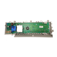
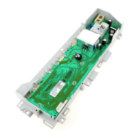
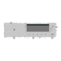
Describes the main and display circuit boards and their functions.
Instructions for programming and updating the main circuit board.
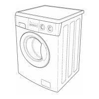
Describes the construction of the welded tub and drum blades.
Instructions on how to arrange the flap for different detergent types.
General characteristics of the noise filter.
Describes the function of the display board and its power supply.
Details the drain pump's construction and operation.
Describes the armoured heating element and its safety fuses.
Describes the NTC probe used for wash temperature control.
Describes the electromechanical door safety interlock.
Describes collector motors used and their speed range.
Explains how the motor operates, including stator winding and brushes.
Details how motor speed is controlled via voltage and TRIAC.
Describes the tachometric generator's role in speed control.
Details the three-phase motor's characteristics.
Explains how power is supplied to the three-phase motor via the inverter.
Describes the inverter for the asynchronous motor.
Explains the anti-foam control procedure.
Describes how solenoid valves control water inlet.
Describes the analogue pressure switch for water level control.
The main electrical circuit diagram itself.
Instructions for removing the worktop.
Lists components accessible from the worktop.
Steps to remove the solenoid valve.
Instructions for removing the top counterweight.
Steps to remove the bellow seal.
Instructions for removing the door hinge secured with rivets or screws.
Steps to detach door hinge secured by rivets.
Instructions for removing and repositioning the door.
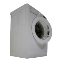
Instructions for removing the back panel.
Lists components accessible from the back panel.
Steps to remove and reassemble the drive belt.
Steps to remove and refit the motor.
Instructions for removing the heating element resistance.
Lists components accessible from the bottom.
Instructions for accessing and removing the drain circuit filter body.
Steps to remove the shock absorbers.
Instructions for removing and re-assembling the front counterweight.
| Brand | Electrolux |
|---|---|
| Model | EWM09311 |
| Category | Washer |
| Language | English |