Do you have a question about the Electrolux EWM1000 and is the answer not in the manual?
Instructions on how to enter the diagnostic mode for the EWM1000 appliance.
Procedure for quickly displaying the last alarm code on the EWM1000 appliance.
Steps to clear the last recorded alarm code from the EWM1000 appliance.
Details the different phases of the EWM1000 diagnostics cycle for component testing.
Guide on how to display and interpret alarm codes stored in the EWM1000 control board.
Reference table listing EWM1000 alarm codes, descriptions, possible faults, and actions.
Schematic diagram illustrating the basic electrical components and connections for EWM1000.
Diagram and explanation for the PTC door locking device in EWM1000 models.
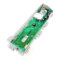
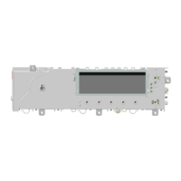
Identification and description of connectors on the EWM1000 main circuit board.
Guidance on identifying components causing burning on the EWM1000 circuit board.
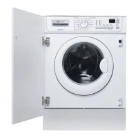
Overview of different control panel designs and configurations for EWM series.
Procedure to access the diagnostic system for EWM models with selectors and buttons.
Steps to enter the diagnostic mode for AEG NexXxt EWM washing machines.
Instructions for accessing the diagnostic system on AEG New Version EWM appliances.
Procedure for entering the diagnostic cycle on DELTA Version EWM washing machines.
Steps to activate the diagnostic mode on CLUB DISPLAY Version EWM appliances.
Instructions for entering the diagnostic system on LCD EWM models without a selector.
Procedure to access the diagnostic mode for EWM LCD models with a program selector.
Details the component testing phases in the diagnostic cycle for EWM models.
Explanation of how to read and interpret alarm codes displayed on EWM appliances.
Table of alarm codes, descriptions, and actions for EWM1000plus, EWM2000EVO, EWM3000NEW.
Schematic of the basic electrical circuit for EWM1000PLUS models.
Basic circuit diagram illustrating the sensor connections for EWM2000EVO models.
Schematic of the basic electrical circuit for EWM3000NEW models with sensors.
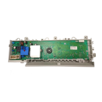
Identification of connectors on the EWM1000plus control board.
Guidance on identifying components causing burning on the EWM1000plus circuit board.
Procedure to enter the diagnostic cycle for ENV06 and EWM series appliances.
Steps to cancel and delete stored alarms on ENV06 and EWM appliances.
Details component testing phases in the diagnostic cycle for ENV06/EWM models.
Explanation of how alarm codes are displayed on different ENV06/EWM versions.
Table listing alarm codes, faults, actions, and resets for ENV06 appliances.
Schematic of the basic electrical circuit for EWM1100 models.
Identification of connectors on the EWM1100 circuit board.
Guidance for identifying components causing burning on the EWM1100 circuit board.
Schematic of the basic electrical circuit for WM EWM2100 models.
Basic circuit diagram for WM EWM2100 models featuring aqua control.
Schematic of the basic electrical circuit for WD EWM2100 models.
Basic circuit diagram for WD EWM2100 models with aqua control.
Identification of connectors on the WM/WD EWM2100 circuit board.
Guidance on identifying components causing burning on EWM2100 WM/WD circuit boards.
Schematic of the basic electrical circuit for EWM25xx models without aqua control.
Second part of the basic circuit diagram for EWM25xx models without aqua control.
Schematic of the basic electrical circuit for EWM25xx WD models without aqua control.
Second part of the basic circuit diagram for EWM25xx WD models without aqua control.
Schematic of the basic electrical circuit for EWM35xx models with aqua control.
Basic circuit diagram for EWM35xx models without aqua control.
Identification of connectors on the WM/WD EWM25xx/35xx circuit boards.
Guidance on identifying components causing burning on EWM25xx/35xx WM/WD circuit boards.
Guidance on identifying components causing burning on WD circuit boards.
| Brand | Electrolux |
|---|---|
| Model | EWM1000 |
| Category | Washer |
| Language | English |