EWM1000
QUICK GUIDE AND APPLIANCES LIST 7/176 599 72 40-80
1.5 Reading the alarms
Proceed as follows to read the last alarm condition stored in the EEPROM on the
control board:
• Access diagnostics mode.
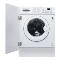
• Irrespective of the type of control board and configuration, turn the programme
selector clockwise to the tenth position.
1.5.1 Displaying the alarm
The alarm is displayed by a repeated flashing sequence of the two LEDs (0.4
seconds ON, 0.4 seconds OFF, with a pause of 2.5 seconds between each
sequence). The buzzer (if featured) sounds a series of “beeps” in synchronization
with the flashing of the LEDs.
• END OF CYCLE indicator → indicates the first digit of the alarm code (family)
• START/PAUSE → indicates the second digit of the alarm code (number
within the family).
These two LEDs are present on all models (though configured in different
positions) and flash simultaneously.
Notes:
• The first letter of the alarm code “E” (Error) is not displayed since it is the same for all alarm codes.
• The alarm code families are expressed in hexadecimal form. In other words:
→ A is represented by 10 flashes
→ B is represented by 11 flashes
→ ...
→ F is represented by 15 flashes
• Configuration errors are displayed by the flashing of all the LEDs (user interface not configured).
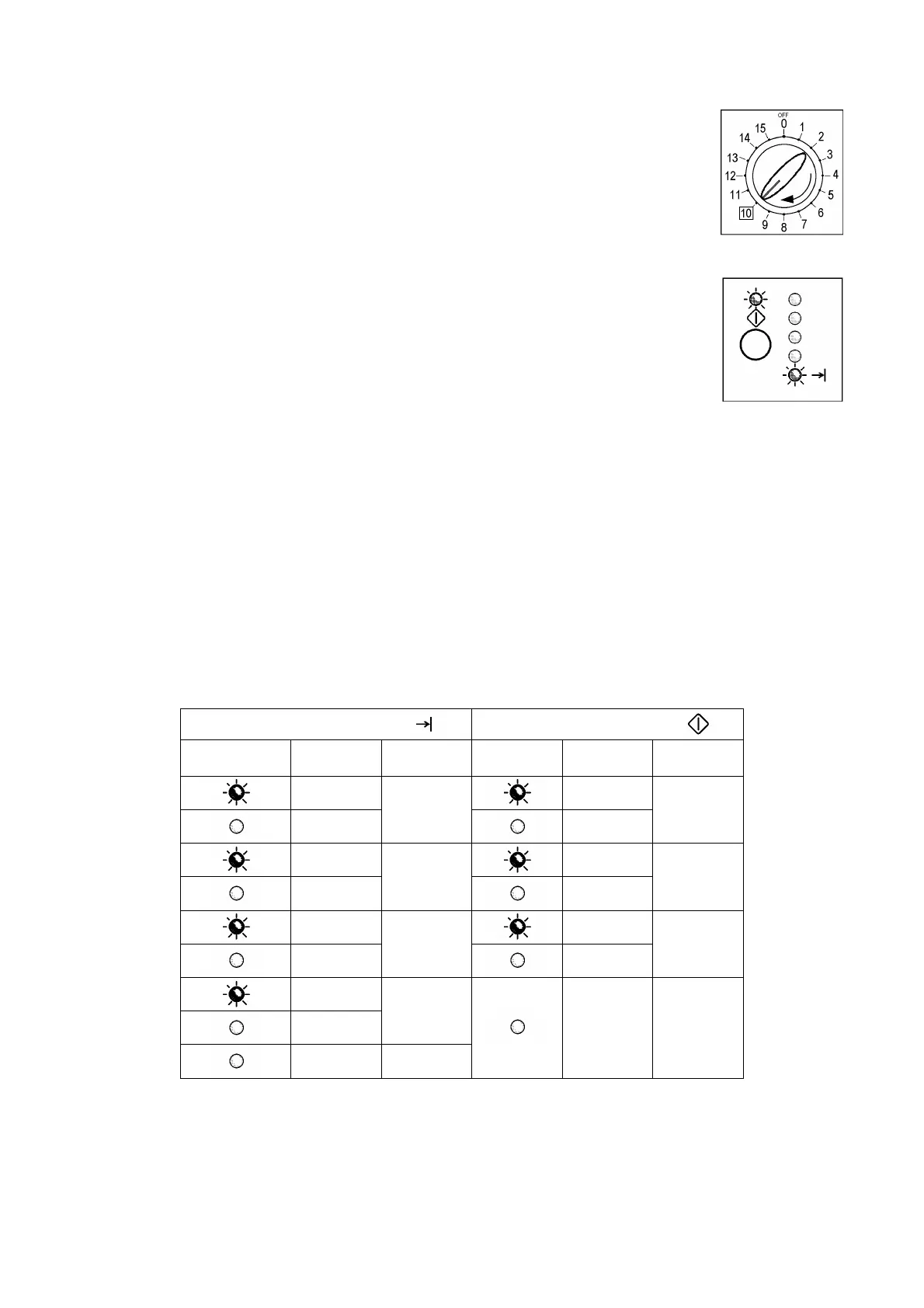
1.5.2 Examples of alarm display
Example: Alarm E43 (problems with the door safety interlock triac) will be displayed as follows:
• four flashes of the END OF CYCLE LED indicate the first digit E43;
• three flashes of the START/PAUSE LED indicate the second digit E43;
END OF CYCLE LED
START/PAUSE LED
ON/OFF
Time
(seconds)
Value ON/OFF
Time
(seconds)
Value
0.4
0.4
0.4
1
0.4
1
0.4
0.4
0.4
2
0.4
2
0.4
0.4
0.4
3
0.4
3
0.4
0.4
4
2.5 Pause
3,3 Pause
1.5.3 Status of alarms during the diagnostics cycle
All the alarms are enabled during the components diagnostics test.