ENV06 EWM11xx EWM21xx EWM25xx/35xx
QUICK GUIDE AND APPLIANCES LIST 76/176 599 72 40-80
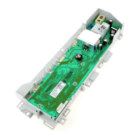
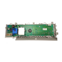
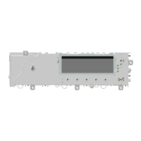
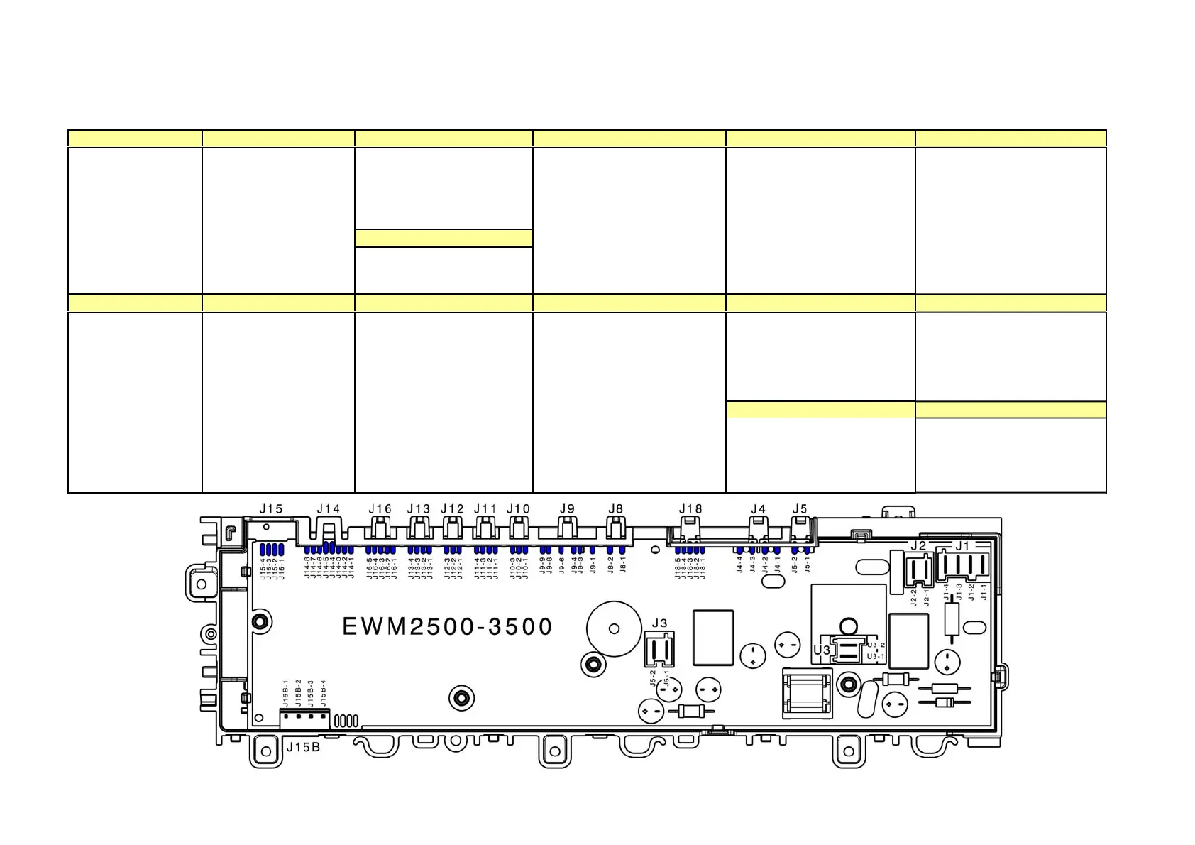
3.21 Connectors on circuit board WM/WD EWM25xx/35xx
J15/J15B J16 J12 J9 J18 J2
Drum positioning system DSP:
J12-1 signal
J12-2 N.C.
J12-3 +5V
J11
Serial interface:
J15-1 ASY_IN
J15-2 ASY_OUT
J15-3 +5V
J15-4 GND
Communication with
WD external board:
J16-1 Vee +12V
J16-2 +5V
J16-3 Rx/Tx
J16-4 GND
J16-5 N.C.
J11-3 Flowmeter (GND)
J11-4 Flowmeter (signal)
JJ9-1 Washing solenoid (triac)
J9-3 Solenoids (line)
J9-4 Solenoids (line)
J9-6 Pre-wash solenoid (triac)
J9-8 NTC temperature sensor
J9-9 NTC temperature sensor
Communication with FCV board:
J18-1 VEE +12
J18-2 +5V
J18-3 Signal
J18-4 GND
J18-5 N.C.
Heating element:
J2-1 Relay
J2-2 Line
J14 J13 J10 J8 J4 J1
J4-1 N.C.
J4-2 Drain pump (triac)
J4-3 Drain pump (line)
J4-4 Circulation pump (triac)
Door lock device:
J1-1 Line (ON/OFF)
J1-2 Line (door)
J1-3 Line (sensing)
J1-4 Triac
J5 U3
LCD Module:
J14-1 RES_SAT
J14-2 CS_SAT
J14-3 Vee (12V)
J14-4 GND
J14-5 +5V
J14-6 SY_OUT
J14-7 SY_IN
J14-8 SY_CLOCK
Weight sensor:
J13-1 (GND)
J13-2 (WS-1)
J13-3 (WS-2)
J13-4 (+5V)
Analogic pressure switch:
J10-1 +5V
J10-2 GND
J10-3 signal
each/condensation solenoid:
J8-1 Line
8-3 Tiac
Drum light:
J5-1 +5V’
J5-2 GND
U3-1 line
U3-2 line (neutral)