16
E.4.3 Sealing Gaps Between Appliances
Follow the instructions supplied with the optional sealing paste
pack.
E.5 Gas, electricity and water connections
(if present, depending on the appliance
and/or model)
• Any installation work or maintenance to the supply system
(gas, electricity and/or water, if present) must only be
carried out by the utility company or an authorised
installation technician.
• Refer to the appliance dataplate for the product code.
• See the installation diagram for the type and position of
appliance connections.
E.6 Gas Connections
E.6.1 Introduction
CAUTION
This appliance is arranged and tested to
operate with G20 gas 20 mbar;
To convert it to another type of gas, follow the instructions in
E.6.6 Conversion to another type of gas paragraph of this
section.
E.6.2 Fume exhaust
• “A1“ type appliances have to be positioned under an
extraction hood to ensure removal of fumes and steam
produced by cooking;
(not relevant for Australian standard).
For AUSTRALIA: the ventilation must be in accordance with
Australian building codes and kitchen exhaust hoods must
comply with AS/NZS1668.1 and AS 1668.2.
E.6.3 Before connecting
1. Make sure the appliance is arranged for the type of gas to
be used.
Otherwise, carefully follow the instructions given in E.6.6
Conversion to another type of gas paragraph of this
section.
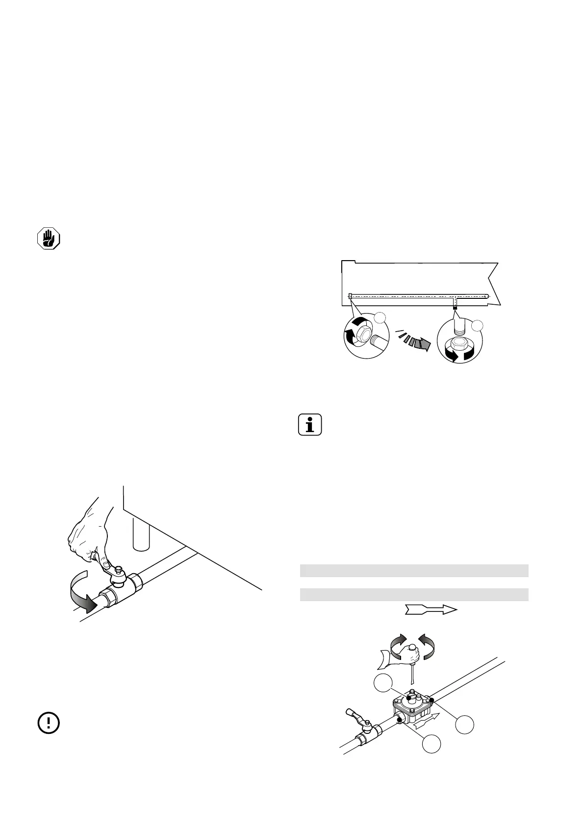
2. Fit a rapid gas shutoff tap/valve ahead of each appliance.
3. Install the tap/valve in an easily accessed place.
4. Clean the pipes to remove any dust, dirt or foreign matter
which could block the supply.
The gas supply line must ensure the gas flow necessary
for full operation of all the appliances connected to the
system.
A supply line with insufficient flow will affect correct
operation of the appliances connected to it.
IMPORTANT
Incorrect levelling of the appliance can affect
combustion and cause malfunctioning.
E.6.4 Connection (depending on the appliance and/or
model)
Monoblock models
1. See the installation diagram for the position of the gas
connection on the bottom of the appliance.
2. Remove the plastic cap protection (if present) from the
gas manifold before connecting.
Countertop models (Only for N9E range)
1. See the installation diagram for the position of the gas
connection on the bottom of the appliance.
2. Remove the plastic cap protection (if present) from the
gas manifold before connecting.
3. Countertop models can be connected to the gas supply
also using the rear connection:
a. operate at the back appliance;
b. unscrew the metal closing plug of the rear connection;
c. screw it tightly onto the bottom connection.
After installation, use soapy water to check connections for
leaks.
NOTE!
Only for Australia: The gas connection is male 1/
2 BSP.
E.6.5 Gas pressure regulator
• The section of the gas supply line must be sufficient to
ensure the gas flow necessary for full operation of all the
appliances connected to the system.
If the gas pressure is higher than that specified or is difficult
to regulate (not stable), install a gas pressure regulator
(accessory code 927225) in an easily accessed position
ahead of the appliance.
The pressure regulator should preferably be fitted horizon-
tally, to ensure the right outlet pressure.
1 connection side gas from mains
2 pressure regulator
3 connection side gas towards the appliance
The arrow on the regulator indicates the gas
flow direction.