2413 14
7
A8A8
C 12345678910111213141516
D1425
D1430
Notice
Date Page
05201053
INSTALLATION
MANUAL
7. Installation
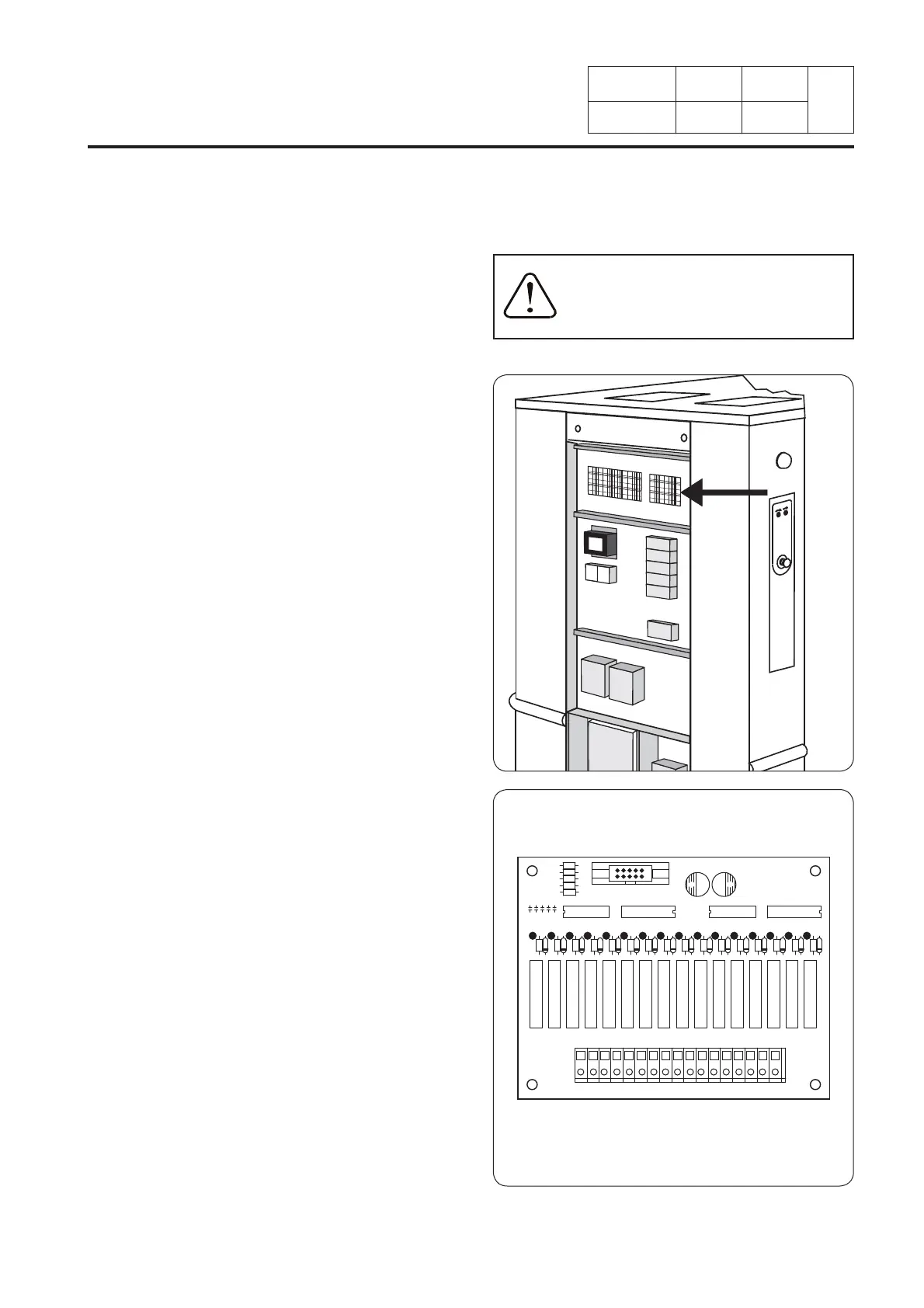
Connection on the A8 output relay card
The output relay card allows to connect from
1 to 16 electrovalves of liquid detergents.
The card is situated on the up right side of
the electric box.
Carry the connection cables by the partition
crossing and the cable through of the
machine.
To connect the wires on the J802 terminal
block, introduce a screwdriver in the upper
aperture to open the cable clamp.
c : common of electrovalves
1 : electrovalve 1
2 : electrovalve 2
3 : electrovalve 3
4 : electrovalve 4
5 : electrovalve 5
6 : electrovalve 6
7 : electrovalve 7
8 : electrovalve 8
9 : electrovalve 9
10 : electrovalve 10
11 : electrovalve 11
12 : electrovalve 12
13 : electrovalve 13
14 : electrov. 14 (contrôlé par niveau d'eau)
15 : electrov. 15 (contrôlé par niveau d'eau)
16 : electrovalve 16 (réserve)
Supply voltage : 250 V~ maximum
Intensity max. : 6 A.
Electrical installation must be
carried out by an authorized
personnel.