Do you have a question about the Electrolux W565H and is the answer not in the manual?
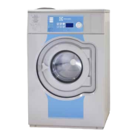
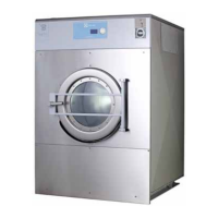
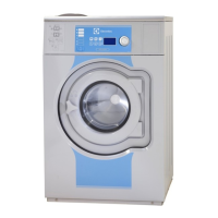
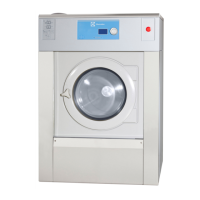
Visual representation of machine components and dimensions for various models.
Detailed specifications including weight, drum volume, speeds, and power.
Details on water, steam, and electrical connections required for the machine.
Sound power levels during wash and extraction cycles.
Ensuring machine functionality and safety after repairs.
Details the components of the door lock system: actuator, micro switch, and emergency button.
Step-by-step instructions for replacing the door lock assembly.
Procedure for accessing and using the emergency door opening button.
Explains the communication and control functions of the motor control unit.
Instructions for safely removing and installing the motor.
Step-by-step guide for replacing the heating element.
Instructions for removing and installing the drum assembly.
Instructions for replacing the drive belt on the drum.
Guidance on adjusting the drive belt tension for optimal performance.
Comprehensive guide for replacing drum bearings.
Explanation of how the drain valve functions using water pressure.
Instructions for replacing the drain valve.
Instructions for replacing the detergent container.
Overview of the control system CPU, its power source, and inputs/outputs.
Details the board connectors and their functions for the control system.
Step-by-step guide for replacing the control system CPU.
Instructions for safely removing and installing the control knob.
Instructions for opening the USB connection port lid.
Details the types of I/O modules installed and their functions.
Information on where to find and identify I/O module parameter software.
Procedure for replacing I/O modules type 1, 11, or 3.
Procedure for replacing I/O module type 2.
Procedure for replacing I/O module type 10.
Procedure for replacing I/O module type 6.
Electrical schematic for external coin meters and central payment systems.
Details starting the machine via a central payment system (230V or 24V).
Central payment or booking system signal for starting the machine.
Functions for detergent signals, pause, empty, and price reduction.
Signal for central booking or payment system to start the machine.
Using connection 3 for price reduction based on time of day.
Overview of troubleshooting, safety, and measurement guidelines.
Guidelines for personnel performing troubleshooting procedures.
Lists error code categories and their minor codes.
Detailed explanations of error codes and their potential causes.
Procedure for inspecting the machine interior for leaks and wear.
| Capacity | 6.5 kg |
|---|---|
| Height | 850 mm |
| Heating power | 6 kW |
| Noise Level (Wash/Spin) | 62/78 dB |
| Width | 60 cm |
| Dimensions (HxWxD) | 850x595x725 mm |