25
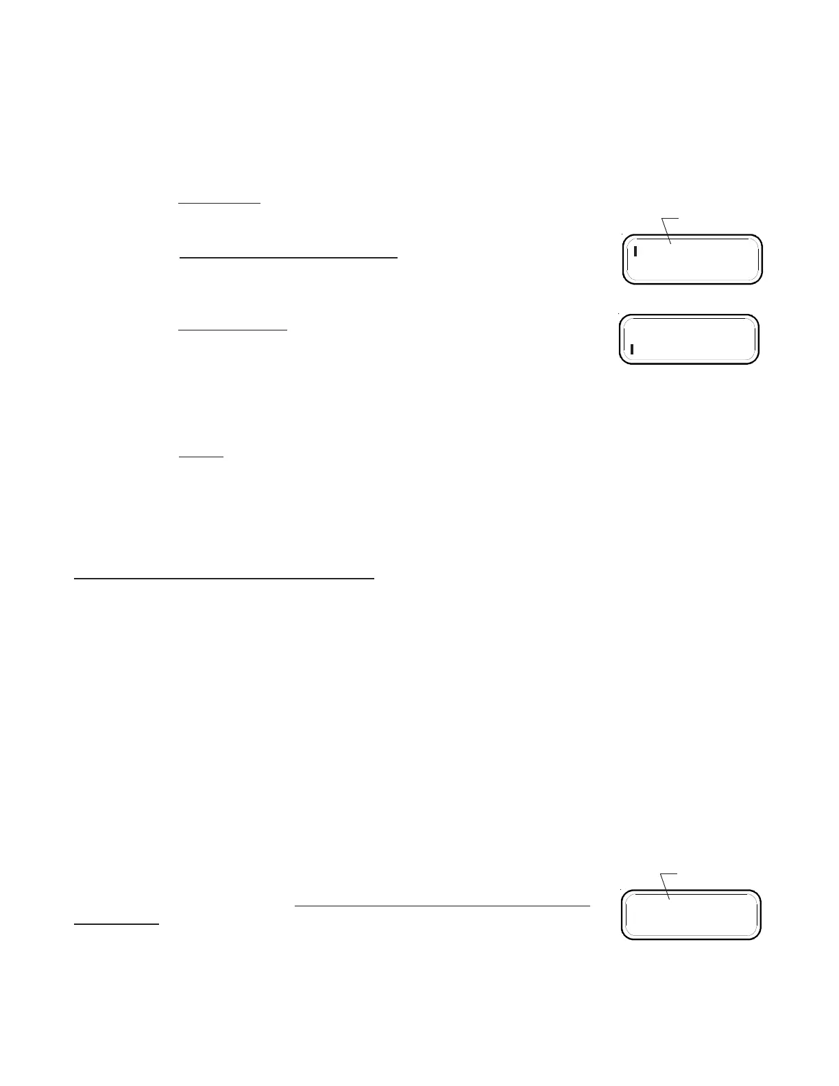
B. Momentarily push both the "F. to DES" and "F. RES" buttons. A bar will appear in the upper left
corner of the display and the left digit will be blinking. You are ready to program the High Pressure
Alarm limit.
C. Set the High and Low Alarm limits using the following procedure:
a)
Select a Digit - The "F. to DES" and "F. RES" buttons move the
blinking digit to the right or to the left.
b)
Increase or Decrease a Digits Count - Moving the "STEP Switch" to
the right will increase the blinking digits count and moving it to the left
will decrease the blinking digits count.
c) Change Functions - The display will toggle between the High and
Low Alarm limits by pushing the right "F. RES" button with the right
digit blinking or by pushing the left "F. to RES" button with the left digit
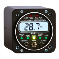
blinking. The High Alarm limit is always displayed with a bar in the
upper left corner of the display and the Low Alarm limit is always displayed with a bar in the
lower left corner of the display.
d) To Exit - To exit the Pilot Programming Settings for the "PRESS" Display Mode, momentarily
push both the "F. to DES" and "F. RES" buttons at the same time. The programmed values will
be stored in memory and no internal batteries or external power are required to store this infor-
mation for life.
PP
PP
P
oo
oo
o
ww
ww
w
erer
erer
er
-Up Pr-Up Pr
-Up Pr-Up Pr
-Up Pr
ogrammable Settings:ogrammable Settings:
ogrammable Settings:ogrammable Settings:
ogrammable Settings:
The FP-5L has eleven Power-Up Programmable Settings. These programmable settings need to be set only
once to configure the instrument to your aircraft, engine and personal preference. The following settings are
available:
1&2. First and Second Full Fuel Levels:
There are two Full Fuel Levels that may be set in the FP-5L. When adding fuel to the FP-5L, the First and
Second programmed Full Fuel Levels may be retrieved automatically. The First Full Fuel Level will be displayed
with a bar in the upper left corner of the display. The Second Full Fuel Level will be displayed with a bar in the
lower left corner of the display.
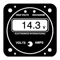
3. K Factor:
The K Factor represents the number of electrical pulses per gallon the FP-5L
receives from the flow transducer. Changing the K Factor changes the accuracy
of the FP-5L. Initially, the K Factor should be set to the value listed for the specific
flow transducer. If the flow transducer came from the factory as a package, the
proper K Factor would have been set in the instrument.
Example: Value listed 68,000 (68,000 pulses per gallon measured on the bench). Set the K Factor on the
FP-5L for the first three digits of the K Factor listed (680).
050
Blinking Digit
060
680
Blinking Digit