1 Introduction
iConnect
Installation Manual
6
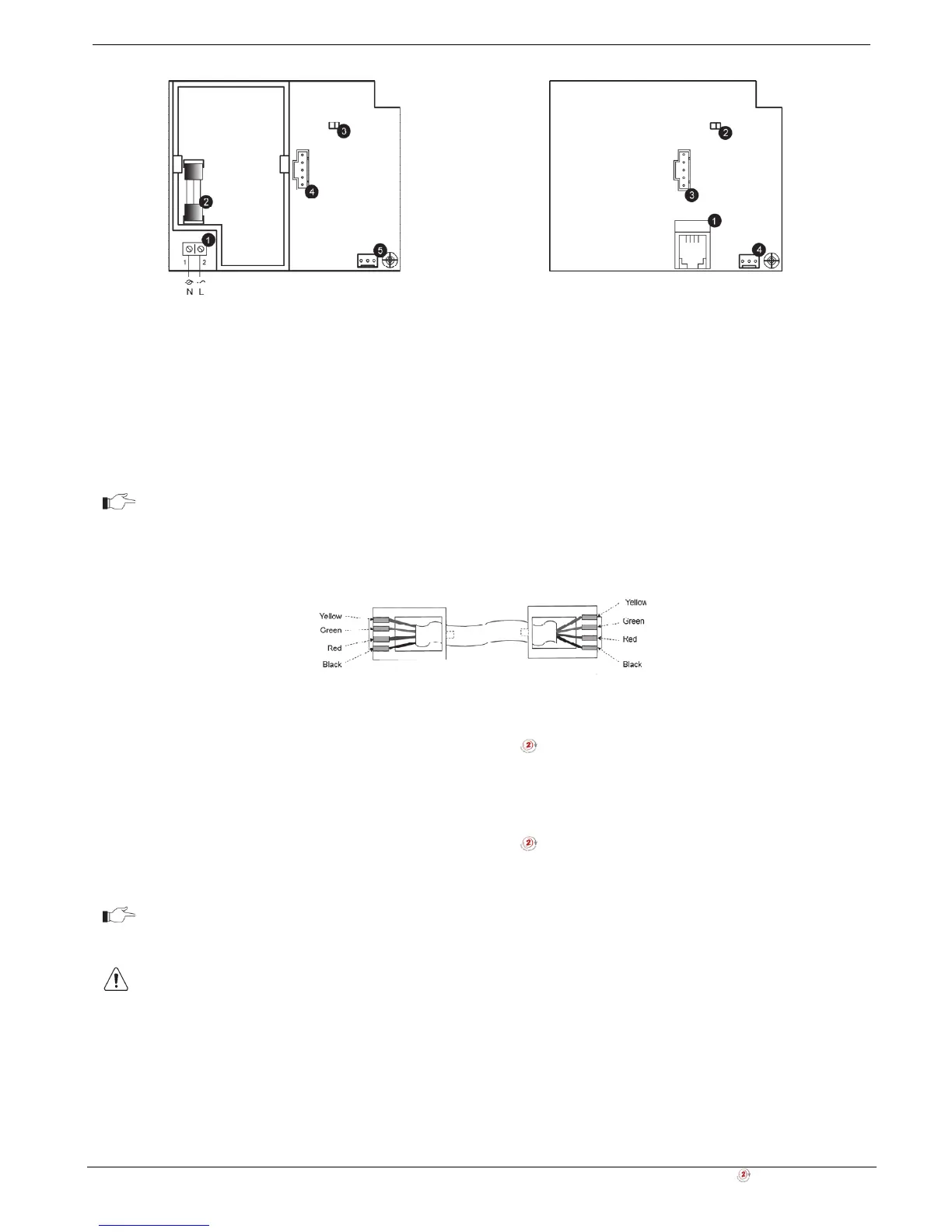
1. Power-line terminal connections to Main
Board (1 - Neutral; 2 - Live)
2. Fuse
3. LED Indicator
4. Flash programming connector
5. Interface connector to Main Board
1. External PLI connector
2. LED indicator
3. Flash programming connector
4. Interface connector to Main Board
Figure 1-5: Home Automation Module (Internal PLI
Module)
Figure 1-6: Home Automation Module (External PLI
Module)
For external X10 PLI, we recommend to use the two-way TTL/CMOS interface such as
XM10E module connected to the HA module with an RJ11 cable wired, as shown below.
Figure 1-7: RJ11 wiring diagram
1.4.3. GPRS/LAN Communication Module
The GPRS/LAN Communication module enables the iConnect
Control System to communicate to the WEB via
cellular networks, perform remote firmware update, send or receive SMS messages, and implement cellular 2-way
audio communication.
1.4.4. LAN/PSTN Module
The LAN/PSTN Communication module enables the iConnect
Control System to communicate to the WEB via
Ethernet, perform remote firmware update, and implement PSTN backup communication with event reporting and
Two-Way Audio (TWA) control.
Do not use VoIP phone lines for communication to the central monitoring station. In certain
cases the system may not transmit alarm signals successfully over the VoIP network.
To reduce the risk of fire, use only No. 26AWG or larger telecommunication wire.