Appendix B: Transmitter Installation
iConnect
Installation Manual
115
I/O Expander Module (EL-4770)
The 2-Way Wireless I/O Expander Module (EL-4770) is an extension module enabling wired devices to be connected to
the iConnect
Control System (SW versions 305 and above). The iConnect Control System supports up-to two 2-Way
Wireless I/O Expander Modules. Each 2-Way Wireless I/O Module supports 8 hardwired zone inputs, 2 auxiliary outputs
and has the capability to control up to 2 PGM devices. Each output or PGM device can be operated in a response to a
wide variety of system events.
The 2- Way Wireless I/O Expander Module is installed outside the Control System in its own dedicated plastic unit
equipped with case open and wall removal tamper protection. The Wireless I/O Module is also provided with its own
power supply and backup battery.
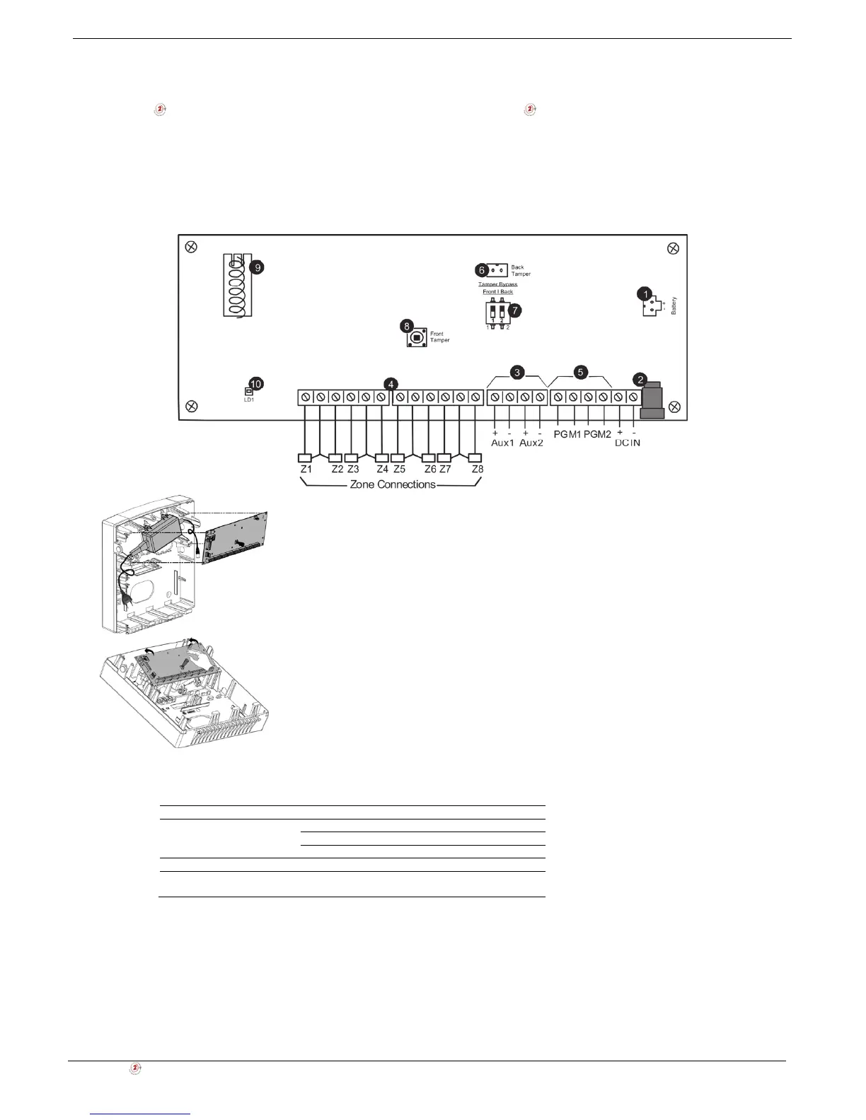
1. Backup battery connector
2. Power input jack (by external AC/DC adaptor)
3. Auxiliary parallel outputs (Aux1-2) for powering detection devices
4. Zone inputs (loop type configurable in programming)
5. Programmable outputs (PGM): dry contact
6. Back tamper switch connector
7. Tamper bypass dip switch
8. Front case tamper switch
9. Antenna (868 or 433)
10. LED indicator
Figure B- 56: I/O Expander Module circuit board and plastic unit
Table B-9: LED Indication
LED State Description
Red On AC and batteries OK
Flashing AC trouble
Off Power not present
Orange Flashing Low battery
Green/Red (tamper open) Flashing Green – Signal reception
Red – Signal transmission
Box & Wall Tamper
Box and wall tamper switches provides extra protection. If the plastic unit is opened the front tamper switch is released
and an alarm is generated. In the event that the plastic unit is removed from the wall, the screw causes the perforated
section of the plastic and attached tamper mechanism metal plate to break and remain attached to the wall. As a result,
the back tamper switch is released and an alarm is generated.
The front tamper switch is located on the front of the circuit board and is depressed via a spring when the front plastic
cover is closed. The back tamper switch is located on the rear side of the back panel and is constantly depressed.