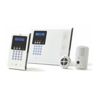
3 Basic System Operation
iConnect
Installation Manual
14
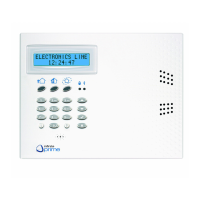
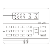
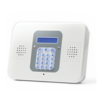
In addition to the front panel keypad, you can install up to four, individually addressed, Wireless LCD keypads. The
layout of the Wireless LCD keypad is similar to the front panel keypad and most of the functionality is identical.
Table 3-3: Front Panel Keypad and Wireless LCD Keypad Functions
Key Symbol used in the
text of this manual
Special function
1 Used to enter symbols in descriptor editing.
0 Used to enter symbols in descriptor editing.
Χ Used to cancel the current selection.
Used to return to the previous menu level.
'√ʹ Used to enter Menu mode.
Used to select the current menu item.
Used to signify the end of an entered value.
Toggles status in Zone Bypass/Unbypass function.
Used to switch Home Automation units or PGM on.
In descriptor editing, used to insert a space before the current character
In phone number editing, used to enter "T", ",", "P", "+", "", "#".
In account number editing, used to enter Hexadecimal digits (A-F).
Toggles item descriptors and default names.
In the event log, toggles the time/date stamp.
Toggles AM and PM when setting the time in 12hr format.
Used to switch Home Automation units or PGM off
In descriptor and phone number editing, used to delete the current character.
Used to scroll backwards in the current menu level.
For Global Chime and Message Center features, used to access shortcuts.
+ (Global Chime shortcut)
+ Χ (Record Message shortcut, front panel keypad only)
+ '
√ʹ (Play Message shortcut, front panel keypad only)
Used to scroll forwards in the current menu level.
During standby, used to scroll through the list of system trouble conditions.
The Wireless LCD Keypad LEDs functionality is identical to those of the Front Panel keypad – see p. 13, 3.2 Front Panel
System Status LEDsError! Reference source not found. shows the layout of the LCD keypad:
3.4. LCD Display
The LCD display provides you with a detailed interface for operation and programming.
Figure 3-2: Typical Standby Display
3.4.1. Standby Mode
Standby mode can be defined as the state the system is in when it is disarmed and not in Menu mode. In Standby mode,
the armed status, system status or banner are displayed. If system status is normal, the current time is displayed.
Table 3-4: Armed Status
Item… Description…
DISARMED The system is disarmed.
FULL ARMED
The system has been armed using the displayed arming method. PART ARMED
PERIMETER ARMED
PART ARMED INST
The system has been armed using the displayed arming method with the
Instant arm feature activated.
PERIM ARMED INST
FULL ARMING
The system is in the process of arming (displayed during exit delay). PART ARMING
PERIMETER ARMING
PART ARMING INST
The system is in the process of arming with the Instant arm feature activated.
PERIM ARMING INST