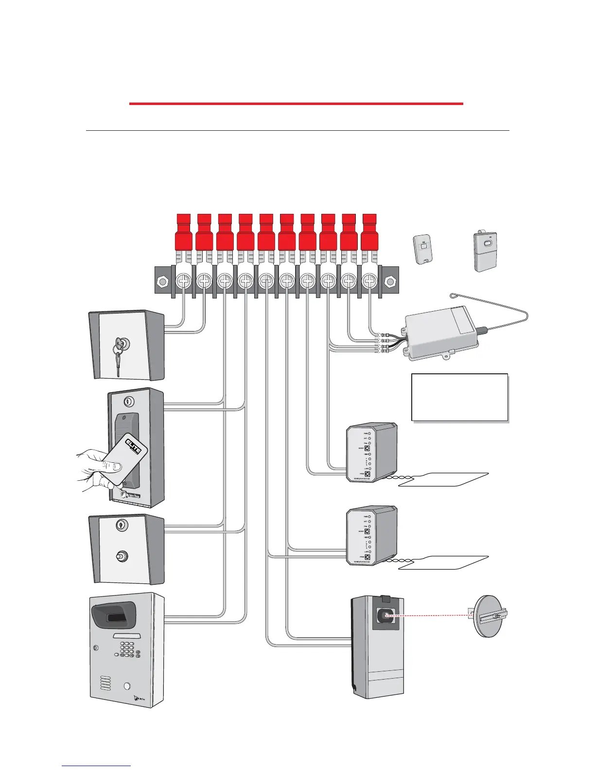
STEP BY STEP INSTALLATION
12345678910
12 VDC Radio Receiver
Transmitters
External “Exit” Loop Detector
External “Safety” Loop Detector
Phone
Entry
Push
Button
Card
Reader
Fire or
Any Key
Switch
Terminal 8 = Grey Wire
Terminal 8 = Black Wire
Terminal 9 = Grey Wire
Terminal 10= Red Wire
4
7
8
0
H
E
L
P
9
1
2
3
5
6
Photo Electric Eye
The radio receiver must be 12 VDC only (Elite Part # A 1099-12V). If you want to use safety
or exit loops, you must use 12 VDC loop detectors only (Elite Part # A 23). The hook-ups
for the radio receiver are as follows: Strike open wires go to 8 and 9 on terminal. Power
supply goes to terminal 10 (positive +) and terminal 8 (negative -). Connections for other
devices are shown below.
STEP 7: Terminal Connections
(Elite Part #A 3060)
(Elite Part #A 3089)
 Loading...