36
EN
N.1 12 mm right adapter (Rif. S)
N.1 12 mm left adapter (Rif. T)
N.1 Galvanized washer (Rif. U)
N.1 Quick release nut (Rif. P)
N.1 left spacer through pin (Rif. Q)
WARNING: adapters ref. R, S, T, U, P, Q are small sized
components and might easily be misplaced or lost. If you
move the hometrainer it's advisable to remove the adapters
and store them in their bag as they might easily slip out during
transport.
Any spare parts are available in our online store or by directly
contacting Elite and/or your country's distributor.
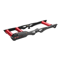
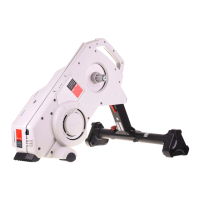
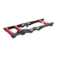
13_ASSEMBLING THE WORKSTAND /
MOUNTING THE UNIT
BICYCLES WITH WHEELS SMALLER THAN 28"
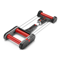
- Place the unit (Ref. B) on a flat surface (Pic.1).
- Place the workstand upside down as shown (Pic.2).
- Pull the selector outwards (Ref. X) and place the plate (Ref.
L) on the stand (Pic. 3-4).
- Tighten the nut (Ref. M) of the plate (Ref. L) and the rubber
supports (Ref. G) with the related screws (Ref. H and I)(Pic.
5-6).
- Rotate the stand and place it on a flat surface, then rotate
the unit inwards until the selector clicks into place. (Pic. 7).
- Tighten the selector completely (Pic. 8-9).
BICYCLES WITH WHEELS LARGER THAN 28”
- Place the unit (Ref. B) on a flat surface (Pic.1).
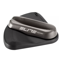
-Unscrew the 2 side covers and mount them on the side
holes (Fig. 10-11).
- Place the workstand upside down as shown (Pic.12).
- Pull the selector (Ref. X) outwards and place the plate (Ref.
L) on the stand (Pic. 13-4)
- Tighten the nut (Ref. M) on the plate (Ref. L) and the rubber
(Ref. G) with the proper screws (Ref. H and I) (Pic. 14-15).
- Rotate the stand and place it on a flat surface.
- Rotate the unit inwards until the selector clicks into place
(Pic. 16).
- Tighten the selector completely (Pic. 17-9).
- Fold the workstand legs (Pic.18).
- Unscrew the two screws and remove the plastic spacer
(Pic.19).
- Subsequently, screw the provided spacer (Ref. C) for
wheels over 28” without applying excessive force (Pic. 20).
- Repeat the same operation for the right spacer
Warning: make sure the spacer is centered on the plastic
support it's screwed in.
Do so by rotating the wooden legs to make sure there are no
obstacles and that it properly leans on the pipe.
14_USE OF THE THRU-AXLE ADAPTER
- Unscrew the thru-axle and remove it from the bicycle
(Pic. 21-22).
- Ø 10mm Hometrainers thru-axle adapter
(Ref. U-R-P) (Pic. 23).
- Ø 12mm Hometrainers thru-axle adapter
(Ref. U-T-S-P) (Pic. 24).
- Screw in the quick release (Ref. E) (Pic. 25).
- Use the spacer if your bicycle does not meet the
requirements of the thru-axle kit (Ref. Q) (Pic. 26-27-28-
29).
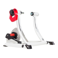
15_FITTING THE BICYCLE
- Make sure the quick release of the bicycle rear wheel is
properly fixed.
- Turn the lever (Ref. W) to the “OPEN” position (Pic.30).
- Position the bicycle by placing it over the center of the roller
(Pic. 31).
- Loosen the external ring (Ref. K) (Pic. 32), then unscrew the
pivot (Ref. J) (Pic. 33) so that the left edge of the bicycle quick
release inserts in the tapered seat (Pic. 34).
- Once the pivot (Ref. J) is positioned, screw the external ring
(Ref. K) to lock the positioning of the bicycle (Pic. 35).
For safer clamping of the bicycle on the stand, make sure
the lever of the quick release is horizontal (Pic.36).
- Close the lever (Ref. W), making sure it starts pressing
the quick release inside the predefined work area; between
55° and 65° (Pic.37).
- If the lever (Ref. W) starts pressing the quick release
in the advanced work position (Pic. 38), screw the right
bushing pin (Ref. Y) (Pic. 39) so that the lever (Ref.W) starts
working inside the predefined work area (between 55° and
65°) (Pic.37).
- Should the lever (Ref. W) start pushing against the quick
release in its pushed back working position (Pic. 40),
untighten the right sleeve pin (Ref. Y) (Pic. 41) so that the
lever (Ref. W) starts working in the predetermined working
area (the one bounded by 55° and 65°) (Pic 37).
- Fold the lever (Ref. W) in the “CLOSE” position by pushing it
downwards with the palm of your hand (Pic. 42)
- Make sure that the over-run lever (Ref. Z) is positioned as
in picture 43.
- Rotate the adjusting knob (Ref. H) clockwise (Pic. 44) until
the resistance unit roller lightly skims the wheel.
- Turn the over-run lever (Ref. Z) 180° to the right (Pic. 45)
and verify wheel compression on the unit support.
- Tyre pressure must be:
7 - 8 atmospheres for racing tyres;
3.5 - 4 atmospheres for MTB tyres.
For particular cases, comply with the pressure
recommended by the tyre manufacturer.