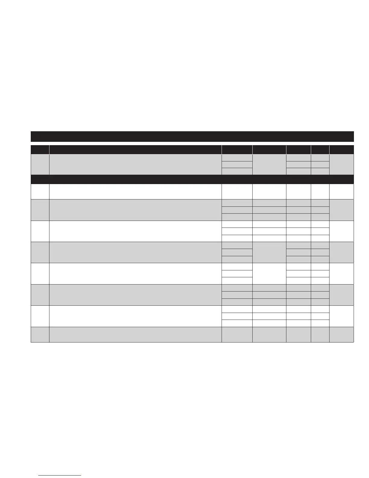
PARAMETERS TABLE
PAR. DESCRIPTION MODEL RANGE VALUE M.U. LEVEL
SP1
Temperature control setpoint SP1. The SEtpoint is visible from the
machine status menu and not from the programming menu.
NTC/PTC
LS1...HS1
0.0 °C/°F
PT100-Tc 0.0 °C/°F
V/I 0 num
CONTROLLER 1 (folder ‘rE1’)
HC1
This sets the controller 1 operating mode.
H (0) = Hot; C (1) = Cold.
ALL H/C H flag Inst
OS1 Temperature value to be added to SP1 if reduced set enabled
NTC/PTC -30.0...30.0 0.0 °C/°F
InstPT100-Tc -30.0...30.0 0.0 °C/°F
V/I -30...30 0 num
dF1
OUT1 activation differential.
The utility stops on reaching the SP1 value (as indicated by control probe) and
restarts at a temperature value equal to T=SP1+dF1 relative to HC1.
NTC/PTC 0.0...30.0 1.0 °C/°F
User/InstPT100-Tc 0.0...30.0 1.0 °C/°F
V/I 0...30 1 num
HS1 Maximum value assignable to setpoint SP1.
NTC/PTC
LS1...HdL
140.0 °C/°F
User/InstPT100-Tc 1350 °C/°F
V/I 199 num
LS1 Minimum value assignable to setpoint SP1.
NTC/PTC
LdL...HS1
-50.0 °C/°F
User/InstPT100-Tc -199.9 °C/°F
V/I -199 num
HA1
Maximum temperature alarm on OUT1.
(See ‘Max/Min temperature alarms’)
NTC/PTC LA1...150.0 140.0 °C/°F
InstPT100-Tc LA1...1999 1350 °C/°F
V/I LA1...150 150 num
LA1
Minimum temperature alarm on OUT1.
(See ‘Max/Min temperature alarms’)
NTC/PTC -150.0...HA1 -50.0 °C/°F
InstPT100-Tc -328...HA1 -199.9 °C/°F
V/I -150...HA1 -150 num
dn1
Switch-on delay. The indicated time must elapse between the request for
activation of the controller 1 relay and switch-on. 0 = not active.
ALL 0...250 0 min Inst