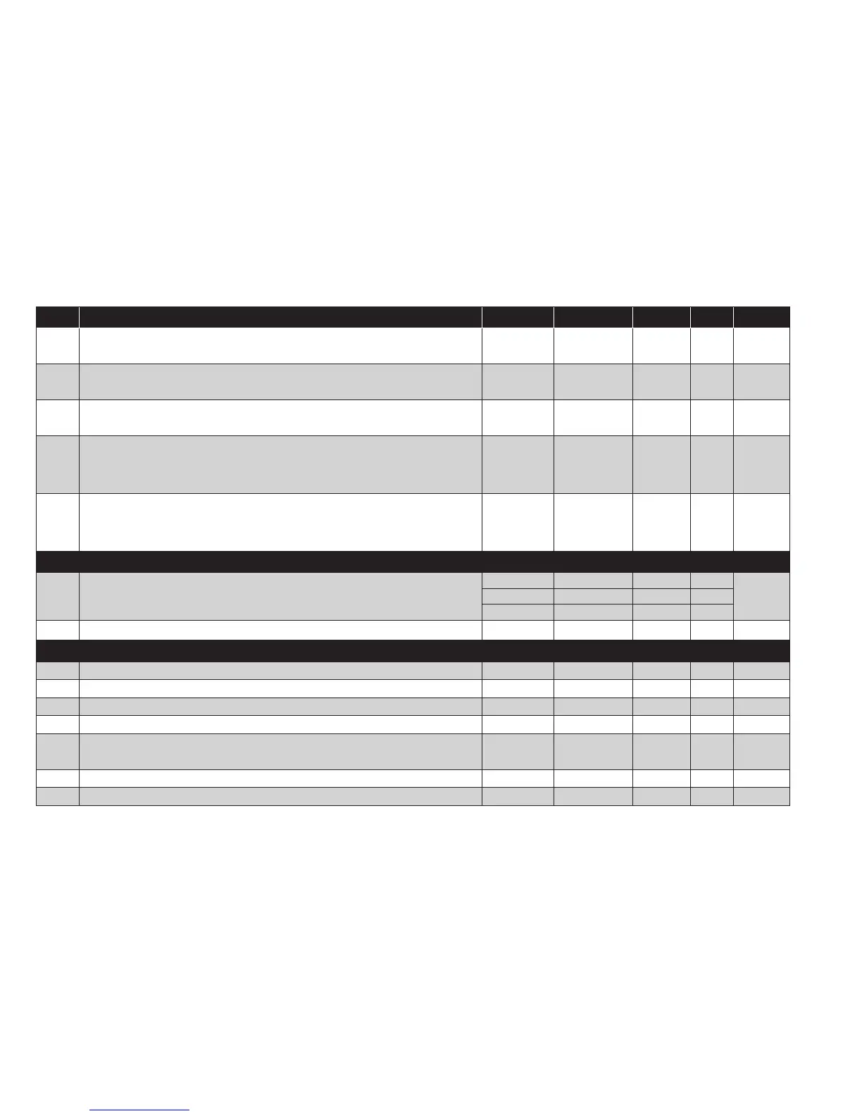
PAR. DESCRIPTION MODEL RANGE VALUE M.U. LEVEL
dO1
Delay time after switching off. The indicated time must elapse between
deactivation of the controller 1 relay and the next switch-on. 0 = not active.
ALL 0...250 0 min Inst
di1
Delay between switch-ons. The indicated time must elapse between two
consecutive switch-ons of regulator 1. 0 = not active.
ALL 0...250 0 min Inst
dE1
Switch-off delay. The indicated time must elapse between the request for
deactivation of the controller 1 relay and switch-off. 0 = not active.
ALL 0...250 0 min Inst
On1
Controller 1 switch-on time in the event of faulty probe.
if On1=1 and OF1=0, the controller remains on;
if On1=1 and OF1>0, the controller operates in Duty Cycle mode.
ALL 0...250 0 min Inst
OF1
Controller 1 switch-off time in the event of faulty probe.
if OF1=1 and On1=0, the controller remains off;
if OF1=1 and On1>0, the controller operates in Duty Cycle mode.
ALL 0...250 1 min Inst
ALARMs (folder ‘AL’)
AFd Alarm differential.
NTC/PTC 1.0...50.0 2.0 °C/°F
InstPT100-Tc 1.0...50.0 2.0 °C/°F
V/I 1...50 2 num
tP Enable all keys to acknowledge an alarm. n (0) = no; y (1) = yes. ALL n/y y flag Inst
COMMUNICATION (folder ‘Add’)
PtS Selection of communication protocol. t = Televis; d = Modbus. ALL t/d t flag Inst
dEA Index of the device within the family (valid values from 0 to 14). ALL 0...14 0 num Inst
FAA Device family (valid values from 0 to 14). ALL 0...14 0 num Inst
Adr Modbus protocol controller address. ALL 1...255 1 num Inst
bAU
Baudrate selection.
48 (0) = 4800; 96 (1) = 9600; 192 (2) = 19200; 384 (3) = 38400.
ALL
48/96/
192/384
96 num Inst
Pty Modbus parity bit. n (0) = none; E (1) = even; o (2) = odd. ALL n/E/o E num Inst
StP Modbus stop bit. 1b (0) = 1 bit; 2b (1) = 2 bit. ALL 1b/2b 1b flag Inst