depending on the device working hours
NOTE: If the manual defrost is already acti-
vated, the automatic defrost request will be
cancelled.
DIAGNOSTICS
PROBE ALARM
An error condition in probe 1 (thermostat
control) causes the following:
• E1 code appears on display
MAXIMUM AND MINIMUM TEMPERA-
TURE ALARM
If an alarm condition occurs and alarm
exclusion times are not running (see alarm
exclusion parameters), the alarm icon
lights up permanently and the relay con-
figured as an alarm is activated. This type
of alarm does not affect the regulating in
progress.
Alarms are considered as absolute
(default) values or as values related to the
Set point (the distance from the Set point
itself) depending on the At parameter. If
the alarms are relative (At=1), parameter
HA is set to positive values and LA to neg-
ative values.
MECHANICAL
ASSEMBLY
The unit has been designed for panel-
mounting: Drill a 71x29 mm hole, insert
the device and fix it in place with the spe-
cially supplied brackets.
The unit operates correctly with an ambient
temperature range of between -5 and 55 °C.
Units must not be installed in excessively
humid and/or dirty locations. Always make
sure that the area next to the instrument
cooling slits is adequately ventilated.
ELECTRICAL
WIRING
For the power supply and relay output, the
device is equipped with Faston connectors
for the electrical cables with a maximum
diameter of 2.5mm
2
(only one conductor
per terminal for power connections): for
terminal capacity, see the label on the
instrument. The relay contacts are voltage
free. Do not exceed the maximum current
allowed. For higher loads, use a suitable
contactor.
Make sure that the power voltage com-
plies with the device voltage. Probes have
no connection polarity and can be extend-
ed using an ordinary bipolar cable (note
that if probes are extended this has an
effect on the electromagnetic compatibili-
ty (EMC) of the instrument: special care
must be used when wiring). The power
supply probe cables should be kept sepa-
rate from the power cables.
TECHNICAL DATA
Front protection: IP65.
Casing: PC+ABS UL94 V-0 resin plastic
body, polycarbonate front, thermoplastic
resin buttons.
Dimensions: front 74x32 mm, 30 mm
depth.
Mounting: panel-mounting with drilling
template 71x29 mm.
Connections:
-3-way 6.3mm FASTON connectors for
relays and power supply
-2-way quick connector for NTC probe
input
Operating temperature: -5…55 °C.
Storage temperature: -30…85 °C.
Operating and storage ambient humidity:
10…90 % RH (non-condensing).
Display range: –50…99 without decimal
point, on display 2 digits + sign.
Analogue inputs: 1 NTC input.
Digital outputs: 1 relay output 5A 1/4 Hp
250 Va SPST
Supply frequency: 50Hz/60Hz
Supply voltage: 230Va
ID 400 2/3
NOTE: The technical characteristics in
this document concerning measure-
ments (range, accuracy, resolution,
etc.) refer to the instrument in the
strictest sense and not to any acces-
sories provided such as probes, for
example. This means, for example, that
an error introduced by the probe is
added to any error that is characteris-
tic of the instrument.
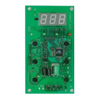
Minimum temperature alarm
Maximum temperature alarm
Temperature lower than or equal to LA (LA with sign)
Temperature lower than or equal to set point+LA (LA only positive)
Temperature higher than or equal to set point+HA (HA only positive)
Temperature higher than or equal to HA (HA with sign)
Maximum temperature alarm
back swing
Minimum temperature alarm
back swing
Temperature higher than or equal to LA+Ad Temperature higher than or equal to set point + LA + Ad
set point-|LA|+Ad
Temperature lower than or equal to set point+HA-Ad
Temperature lower than or equal to HA-Ad
Temperature expressed as an absolute value (par “At”=0)
Abs(olute)
Temperature expressed in relation to set point
(par “At”=0) reL(ative)
if At=reL(ative) LA must be negative: therefore set point+LA<set
point because set point+(-|LA|)=set point-|LA|
MINIMUM AND MAXIMUM ALARMS