DISCLAIMER
This document is exclusive property of Eliwell Controls S.r.L. and cannot be reproduced and circulated unless
expressly authorized by Eliwell Controls S.r.L. Although Eliwell Controls S.r.L. has taken all possible measures
to guarantee the accuracy of this document, it declines any responsibility for any damage arising out of its
use.
The same applies to any person or company involved in preparing and writing this manual. Eliwell Controls
S.r.L. reserves the right to make any changes or improvements without prior notice and at any time.
RESPONSIBILITY AND RESIDUAL RISKS
Eliwell Controls S.r.L. shall not be liable for any damages
deriving from:
• installation/use other than that prescribed and, in
particular, which does not comply with the safety standards
specified in the regulations and/or those given herein;
• use on boards which do not guarantee adequate protection
against electric shock, water or dust when assembled;
• use on boards which allow dangerous parts to be accessed
without the use of tools;
• tampering with and/or alteration of the product;
• installation/use on boards that do not comply with the
standards and regulations in force.
PAR. DESCRIPTION
RANGE DEFAULT
U.M.
PARAMETERS
CONDITIONS OF USE
PERMITTED USE
For safety reasons the instrument must be installed and used
in accordance with the instructions supplied.
Users must not be able to access parts with dangerous
voltage levels under normal operating conditions. The device
must be suitably protected from water and dust depending
on the specific application and only be accessible using
special tools (except for the front keypad).
The device is ideally suited for household use and/or similar
use in the refrigeration sector and has been tested with
regard to safety in accordance with the European
harmonized reference standards.
• for its construction, as an automatic electronic control
device to be independently mounted;
• for its automatic operating features, as a 1 B-type operated
control type device;
• as a Class A device in relation to the category and structure
of the software.
UNPERMITTED USE
The use of the unit for applications other than those
described above is forbidden.
It should be noted that the relay contacts supplied with the
device are functional and therefore exposed to potential
faults. Any protection devices required to comply with
product requirements or dictated by common sense due to
obvious safety reasons should be installed externally.
ccoodd.. 99IISS4433008866--11 -- IIDD440000 -- rreell.. 0088//0099 -- EENN --
©© EElliiwweellll CCoonnttrroollss ss..rr..ll.. 22000099 AAllll rriigghhttss rreesseerrvveedd..
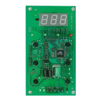
TERMINALS
1-2 Compressor relay output
2-3 Power supply 230Va
Probe Quick connector for NTC probe
SP
Set Point
LS...HS 20 °C/°F
dF
Differential
1...30 2 °C/°F
HS
Maximum Set Point value
LS...99 99 °C/°F
LS
Minimum Set Point value
-50...HS -50 °C/°F
dn
Start-up delay
0...10 0 min
di
Delay between start-ups
0...99 0 min
Od
Output delay from power-on
0...99 0 min
dt
Interval between defrosts
0...99 6 hours
dE
Defrost time out
1...99 30 min
At
Determines if “LA” and “HA” are
0/1 0 flag
expressed as an absolute value or as a
differential compared with the set point:
0 = absolute value
1 = value related to set point
Ad
Alarm Set Point differential
1...50 2 °C/°F
HA
Maximum alarm. Temperature
LA...99 50 °C/°F
limit (whose absolute or relative
value status is controlled by “At”)
above which the alarm is
activated.
LA
Minimum alarm. Temperature
-50...HA -50 °C/°F
limit (whose absolute or relative
value status is controlled by “At”)
below which the alarm is
activated.
tA
Alarm signal delay time
0...99 0 min
PA
Password 1 (blocks activations and
0...99 0 num
parameters changes)
CL
Cell probe calibration
-12...12 0 °C/°F
dL
Display Lock
0/1/2 0 num
dr
Selection °C/°F
0/1 0 flag
0 = °C; 1 = °F
re
Firmware release
0...99 0 num
tb Map
Code
0...99 1 num