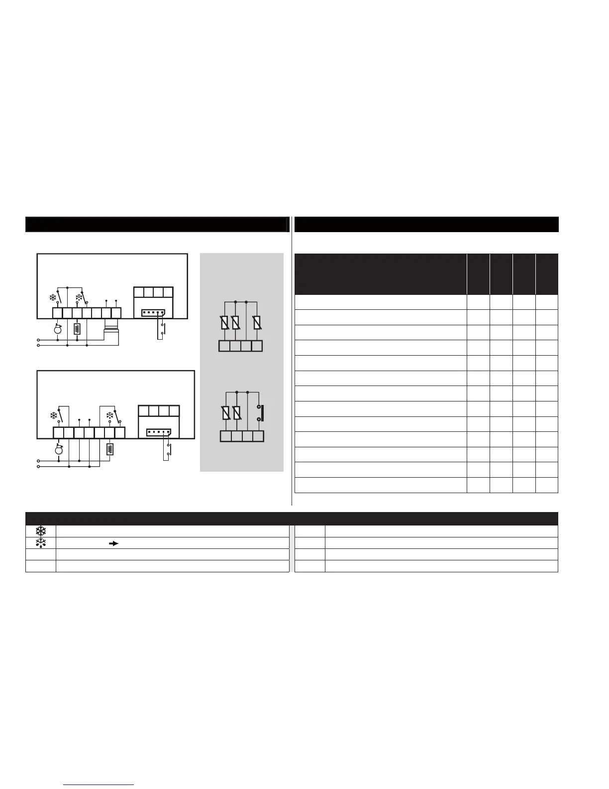
IDPLUS 971 CONNECTIONS
IDPlus 971: TERMINALS
1-2: Compressor relay TTL TTL Input or Digital Input 2
Defrost relay 2-3-4: 12Va or 5-6-7: 230Va
10-9 Probe Pb1
Supply
6-7: models 12Va or 3-4: models 230Va
10-8 Probe Pb2
N-L 230V
a power supply 10-11 Digital Input 1/ Pb3 probe
F = Functions
H = Inputs and Outputs
R = Relay Output
APP.
1
APP.
2
APP.
3
APP.
4
Cold application X X X X
F - End defrost by time X X
F - End defrost by temperature X X
F - Alarm on Pb1 X X X X
F - Compressor OFF X
H - Pb1 present X X X X
H - Pb2 present X X
H - Pb3 / D.I.1 enabled D.I. D.I. D.I. D.I.
H - Buzzer X
R - Compressor X X X X
R - Heating elements X X
R - Fans X
R - Alarm X
Application settings
version with Pb3
(H11=0 and H43=y)
version with D.I.1
(H11≠0 and H43=n)
Pb3
9
10
Pb1
11
8
Pb2
D.I.1
9
10
Pb1
11
8
Pb2
Probe
connections