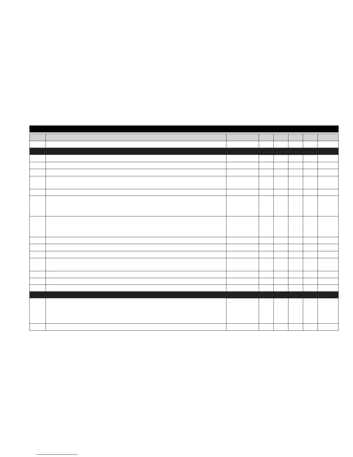
PAR. DESCRIPTION RANGE APP1 APP2 APP3 APP4 M.U.
SEt Temperature control SEtpoint LSE ... HSE 0,0 0,0 0,0 0,0 °C/°F
COMPRESSOR (“CP” folder)
diF diFferential. Compressor relay activation differential 0,1...30,0
2,0 2,0 2,0 2,0
°C/°F
HSE Higher SEt. Maximum value that can be assigned to the Setpoint LSE...302 99,0 99,0 99,0 99,0 °C/°F
LSE Lower SEt. Minimum value that can be assigned to the Setpoint -58,0...HSE -50,0 -50,0 -50,0 -50,0 °C/°F
OSP
Temperature value to be added to the Setpoint if reduced set enabled
(Economy function)
-30,0...30,0 3,0 0,0 0,0 3,0 °C/°F
Hc Control mode. “H” = Hot, “C” = Cold C/H C C C C flag
Ont
Controller on time for faulty probe.
If Ont = 1 and OFt = 0, the compressor remains on;
if Ont=1 and OFt>0 it runs in duty cycle mode
0 ... 250 0 0 0 0 min
OFt
Controller off time for faulty probe.
If OFt = 1 and Ont = 0, the controller remains off;
if OFt = 1 and Ont>0, it operates in duty cycle mode
0 ... 250 1 1 1 1 min
dOn Compressor relay activation delay after request 0 ... 250 0 0 0 0 secs
dOF Delay after switching off and subsequent activation 0 ... 250 0 0 0 0 min
dbi Delay between two consecutive compressor activations 0 ... 250 0 0 0 0 min
OdO
(!)
Delay in activating outputs after the instrument is switched on or after a power failure.
0 = not active
0 ... 250 0 0 0 0 min
dcS Deep Cooling cycle Setpoint -58,0...302 0,0 0,0 0,0 0,0 °C/°F
tdc Deep Cooling cycle duration 0 ... 255 0 0 0 0 min*10
dcc Defrost activation delay after a Deep Cooling cycle 0 ... 255 0 0 0 0 min
DEFROST (“dEF” folder)
dtY
Type of defrost.
0 = electrical defrost;
1 = reverse cycle defrost;
2 = defrost independent of compressor
0/1/2 0 0 0 1 num
dit Interval between the start of two consecutive defrost cycles 0 ... 250 6 6 6 6 hours
TABLE OF INSTALLER MENU PARAMETERS (IDPLUS 974)