ERPB2-8C, ERPB2-8RAC, ERPBV2-8C, ERPBV2-8RAC, LRPB2-8C, LRPB2-8RAC
97924C (Rev. A - 03/03)
Page 3
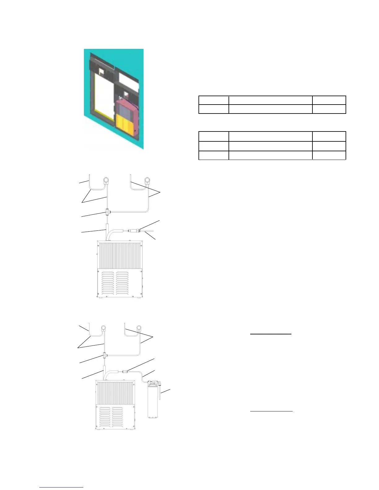
Figure 4 - LRPB Tube Routing
1. Install chiller: Remove front panel of chiller. Remove
and discard cardboard inner pack from between
compressor and side panel. Slide chiller onto the
shelf and position it to the left as per dimensions in
Figure 1.
Note: Building construction must allow for
adequate air flow on both sides, top and
back of chiller. A minimum of 4 (102mm) on
both sides and top is required. See chiller
installation for additional instructions.
2. Make water supply connections. Install a shut-off valve
and union connection to building water supply (valve and
union not provided). Turn on water supply and flush the
line thoroughly.
3. ERPB Models: Make connection between remote chiller
and building supply line. Inlet port is marked on the chiller
(1/4 O.D. copper tube). Bend the copper tube (provided)
at an appropriate length from chiller to opening in frame.
Install the in-line strainer (provided with chiller) by pushing
it until it reaches a positive stop, approximately 3/4 (19mm)
on the marked chiller inlet port. Connect building supply
line to strainer. (See Figure 3)
Caution: DO NOT SOLDER tubes inserted
into the strainer as damage to
o-rings may result.
4. LRPB Models: Mount filter head assembly to side of
chiller (See Figure 4). Make connections between filter
and building supply line (3/8 O.D. tube not porvided).
Inlet port is marked on the chiller (1/4 O. D. copper tube).
Install a 1/4 x 1/4 union (provided) on the marked chiller
inlet port. Insert the 1/4 poly tubing (provided) into the
fitting on filter and connect the union to the chiller.
(See Figure 4)
Caution: DO NOT SOLDER tubes inserted
into the strainer as damage to
o-rings may result.
Special Tools
Item Description Quantity
NONE
Additional Materials
Item Description Quantity
1 Unplated copper inlet pipe
2 Service Stop
REQUIRED TOOLS AND MATERIALS
These tables show special tools and/or
additional materials (not provided) which are
necessary to complete installation of these
units:
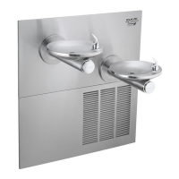
Figure 2 - Chiller Installation
CHILLER
INLET
CHILLER
OUTLET
25
24
26
TO BUBBLER
24
Figure 3 - ERPB Tube Routing
TO BUBBLER
24
25
37
24
24
CHILLER
OUTLET
WATER
INLET
 Loading...