26
MODEL 520
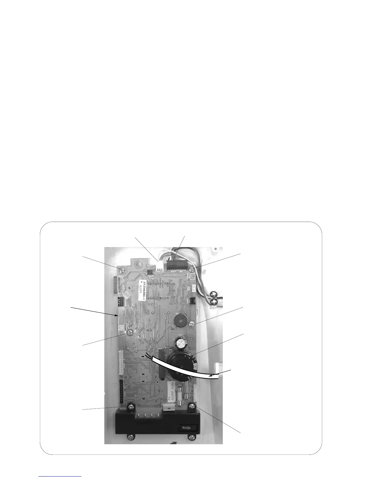
REPLACING PRINTED CIRCUIT BOARD A
TO REMOVE:
1. Remove the front cover (see page 6 and 7).
2. Unplug the connectors from the board "A".
3. Remove the 6 screws and remove board "A".
NOTES: TO DISCONNECT THE CONNECTORS:
1. Grasp the connector directly with your fingers and pull.
Do not pull on the lead wire, as this may damage the contact sleeve inside the connector.
2. When disconnecting the machine socket and power transformer connectors, pull them while
pushing them toward the a board to unlock them.
TO INSTALL:
4. To install, follow the above procedure in reverse.
NOTES:
When installing board "A" in the machine.
The transformer wire should not pass over the capacitor when board "A" is installed.
If the cord is resting on the capacitor, it may interfere the pattern selector button after the front
cover is installed.
Printed circuit
board "F"
Setscrew
Setscrew
Printed circuit board "A"
Setscrew
Setscrew
Setscrew
Setscrew
Slide volume
connector
Capacitor
The transformer cord should
not pass over the capacitor
when board "A" is installed.