Checking the crimp result
To make sure the tool has made the required deformation for the specifi c cable connector, securing mechanical
strength and fi rst-rate electrical contact properties, the crimp should be inspected.
For Cu-terminals and -connectors, the following applies:
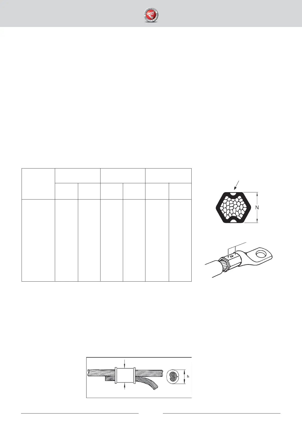
• The check of the gauge measure N is to be made on the hexagon sides that have pattern
stampings from the press dies.
• Check with a slide calliper on one or both sides of the stamp and compare with the N-gauge
measure in the table below.
• Should the test result exceed the N-gauge measure in the table below after properly performed
crimping, contact nearest authorized Elpress Service shop.
C-sleeves from Cu should be checked with regard to the size ”h”. The ”h”-size is best measured with a slide
calliper on the maximum height of the crimped oval. The measurement should be compared with those in the
table on the next page.
Should the ”h”-size be exceeded following a properly performed crimping operation, contact nearest authorized
Elpress Service shop.
IMPORTANT! When processing C-sleeves, there must always be conductor strands outside the outer
edges of the C-sleeve. The minimum length of the strands sticking out must correspond to
at least 60 % of the diameter of the conductor.
16
Cu-
conductor
mm
2
KRF/KSF types KRD/KSD types KRT/KST types
Press-
die no
Press-
die no
Press-
die no
Max N
mm
Max N
mm
Max N
mm
10
16
25
35
50
70
95
120
150
185
240
300
400
8
9
11
13
14,5
17
20
22
25
27
30
32
38
6,3
7,3
8,8
10,2
11,4
13,4
16,4
16,3
20,3
20,5
23,3
24,5
30,5
-
8
9
11
12
14
16
19
22
25
27
30
32
-
6,3
7,3
8,8
10,2
11,6
13,2
15,4
16,3
20,3
20,5
23,3
24,5
7
8,5
10
12
14
16
18
19
22
24
26
30
32
5,9
7,5
8,2
10,2
11,6
13,2
14,0
15,4
16,3
17,7
19,5
23,3
24,5
Measuring
points
Pattern stamp
Measuring points