Quick Start Guide Flatpack2 PS System, 4U, SP2-based 356825.103, 2v0 -2011-09
12
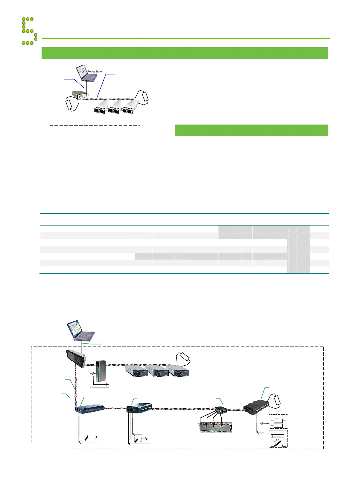
CAN Bus Termination
Flatpack2 systems are shipped from factory with the
CAN bus already terminated with 120 resistors.
To ensure a correct bus communication and avoid data
reflection, you must always terminate the CAN bus with
two 120 resistors, one at each end of the line (60 bus
impedance). The figure shows a Flatpack2 system
communicating via the CAN bus.
CAN Bus Addressing
All rectifiers and control units (controllers and CAN nodes) connected to the Eltek Valere’s CAN bus must
have a unique address or ID number. The power system’s master controller assigns automatically the
rectifiers’ addresses (software assignment). The master controller registers the rectifiers’ ID numbers – or
CAN bus address (01, 02 ...) – together with their Serial Numbers.
The power system’s control units make use of DIP switches for configuring their unique CAN bus ID
number (hardware assignment). The only exception is the Compack and Smartpack2 Master controllers,
which have factory assigned specific ID numbers <1>and <11> (not changeable).
In the control system’s CAN bus, you can address a maximum of 14 CAN nodes of each type, 8 Smartpack
and Smartpack2 Basic controllers and 8 Smartnode units. See table below:
For DIP switch configuration, refer to actual control unit’s guide or to WebPower Help.
The figure shows a Flatpack2 DC power system with Smartpack2-based control system and 4 CAN nodes
to implement additional digital inputs, relay outputs or similar functionality.
Appendix Communication
120
Flatpack
DC Power System
End-of-Line
Resisto
End-of-Line
Resisto
120
CAN bus
(twisted-pair internal
CAT5 cable)
USB
-B cable
(standard)
01 02
n
1
Flatpack
DC Power System
CAN bus
(twisted-pai
CAT5 cable)
33
Battery string #1
Battery Monito
ID Numbe
I/O Monitor2
81
Load Monitor
49
End-of-Line
Resisto
120
Fuses
Fuse Monitoring
Configurable Inputs
Current Monitoring
Sense Inputs
Shunts
larm Outputs NC-C-NO
Config. Inputs
End-of-Line
Resisto
120
Smartpack2
Basic Controller
Flatpack
HE
Rectifiers
01 02 n
1
Internal System Monitoring
Smartpack2
Master Controlle
Ethernet cable (LAN)
WebPower
(web-based user interface)
I/O Monitor
82
larm Outputs NC-C-NO
Config. Inputs
Temp, Fan Speed Mon & Ctrl
Number of nodes >>
Control Units’ Name
1
2 3 4 5 6 7 8 9 10 11 12
13
14
15 16
Smartpack & Smartpack2 Basic Controllers 1 2 3 4 5 6 7 8
9 10 11 12 13 14 15 16
<< ID #
Smartnode Control Units 17 18 19 20 21 22 23 24
25 26 27 28 29 30 31 32
<< ID #
Battery Monitor CAN nodes 33 34 35 36 37 38 39 40 41 42 43 44 45 46
47 48
<< ID #
Load Monitor CAN nodes 49 50 51 52 53 54 55 56 57 58 59 60 61 62
63 64
<< ID #
**
65 66 67 68 69 70 71 72 73 74 75 76 77 78 79 80
<< ID #
I/O Monitor & I/O Monitor2 CAN nodes 81 82 83 84 85 86 87 88 89 90 91 92 93 94
95 96
<< ID #
Mains Monitor CAN nodes 97 98 99 100 101 102 103 104 105 106 107 108 109 110
111 112
<< ID #
ID numbers formatted in grey italics are not available due to software constraints.
** Only 4 of the 8 mounted DIP switches may be used (max. 14 Load Monitors may be connected).