Quick Start Guide Flatpack2 PS System, 4U, SP2-based 356825.103, 2v0 -2011-09
4
Installation Steps
Check off in the Installation Check List, that you find in the pullout section o
this folder. Also, refer to the system’s specific drawings.
For external AC fuses and AC input cable ratings, refer to your site’s AC
supply specification. Read also our external AC fuse recommendations
in section “Appendix”. In general, a site with better AC supply qualit
(stable nominal voltage) may use smaller breakers.
Installation
200 mm
600 mm
Location of tools
in IFC cabinets
Location of tools
in IFC cabinet’s bottom
(Lifting plates, leg adjusting plates and
open-ended spanner or wrench)
Fastening screw for tools
compartment’s cove
Cover, lifted
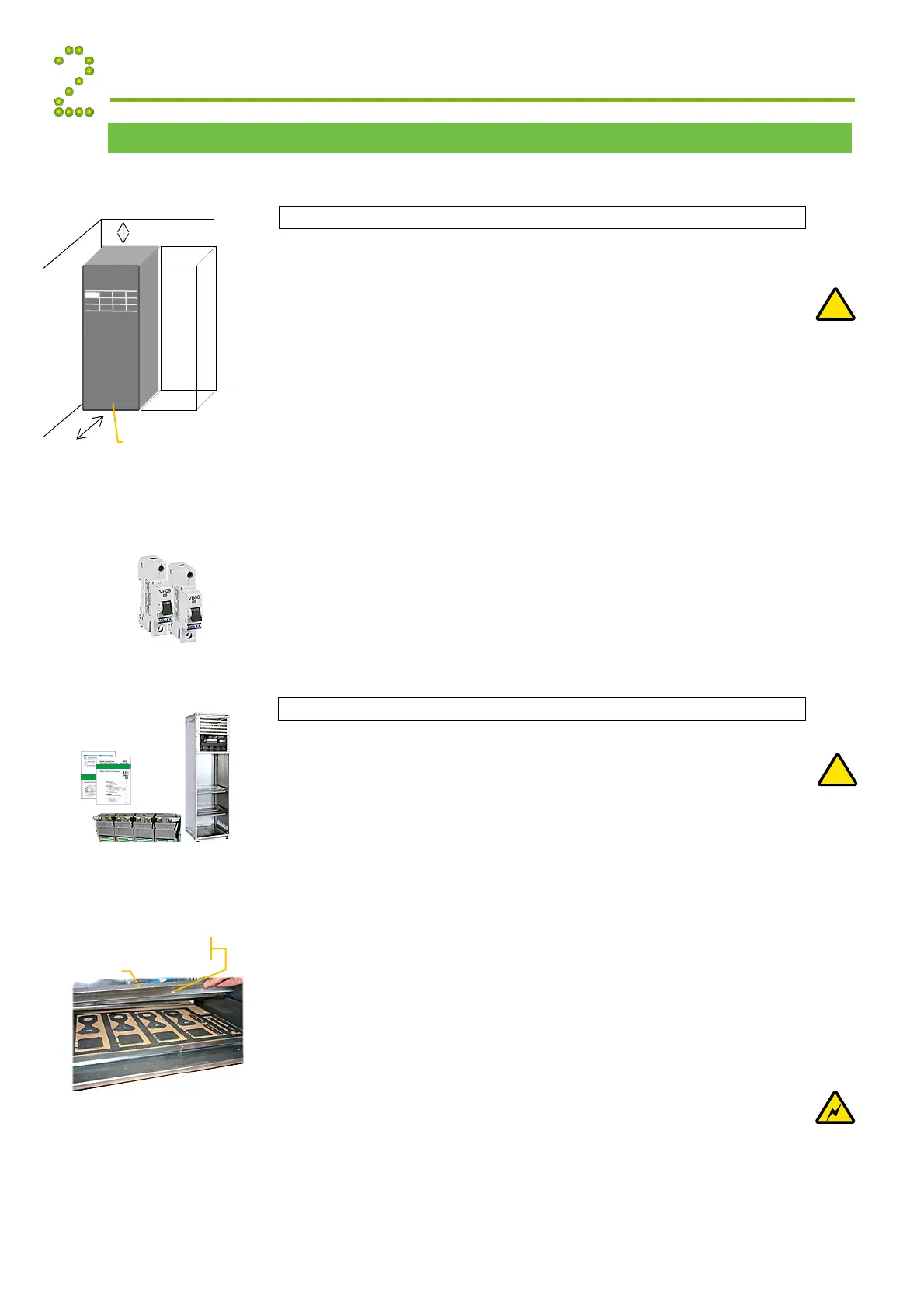
Preparing the Installation Site
Begin preparing the following:
1 Organize the installation site
o Min. clearances for cabinet access: 60 cm in front, 20 cm on top
o Levelled surface able to support 600 kg (cabinetized systems)
o Explosive atmospheres are to be avoided. Ensure suitable
ventilation
o 60V systems are only to be installed in Restricted Access
Locations (RAL)
2 Prepare the installation tools
o Use insulated tools suitable for telecom installations
3 Prepare AC Supply: AC input cable(s) and fuses
o Correct type AC supply is available
o External AC fuses have correct rating
o AC input cable(s) are sized correctly
EMC
Regard
!
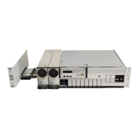
Mechanical Installation Power is OFF!
Carry out the following:
4 Remove packaging and check equipment
o Check you have received all the parts, correct cabinet,
documentation, batteries (if applicable), etc.
o Inspect the equipment for physical damage (report any damages)
o Leave rectifier modules in their packaging or in the selves, if
factory installed. To be installed under commissioning
5 Remove top cover and dummy front panels
o Cable entry from the top. Connection terminals are located
behind the upper dummy panels
o Battery shelves (if any) are placed behind the lower panels
6 Position and fasten the cabinet or subassembly
o Cabinets are floor-mounted on levelled surface. Adjust the legs if
necessary. If the cabinet must be fastened, unscrew the legs and
use suitable bolts to fasten it to the floor
o Subassemblies are fastened in existing 19” or in ETSI cabinets,
using brackets. Mount the support & heat deflecting plate under
the lower power shelf
7 Mount the batteries on the shelves
o Start (if applicable) placing the batteries on the lower shelf first,
and continue upwards
o Do not terminate the battery cables yet!
Device
Hazard
!
Electric
Shock
Flatpack2 PSS, batteries, Doc.
Chart, Spec. Drawings