www.eltekvalere.com
Headquarters:
Eltek Valere
Gråterudv. 8, PB 2340 Strømsø, 3003 Drammen, Nor
Phone: +47 32 20 32 00 Fax: +47 32 20 32 10
Form 170-gb-v7-C01_356825-103_qstart_flatpack2-4u-distr-sp2-syst_2v0.docx_ mafe-2010-05-25
COMMISSIONING PROCEDURE
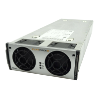
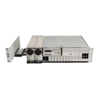
System Data Flatpack2 PS System
Supplier’s Order No.: Flatpac
ower
upply System, type:
rticle No.:
Site, name:
Serial No.: Software, version No.:
Rectifiers, type & number of:
C Input Voltage, measured: Battery Type:
Battery Capacity:
Commissioning carried out by, name:
Pre-Start Check Power is OFF!
CHECK FOLLOWING: OK
1. Flatpack2 system installation is completed; The Flatpack2 Installation Check List is filled in.
All cabling is securely terminated with correct polarity
2. All battery and load MCBs/ fuses are disconnected
3. AC input cable(s) and AC earth wire (PE) are terminated
4. Site specific parameters and settings are known
5. AC supply and all MCBs/ fuses are switched OFF
Start-up, No-Load & Load Adjustments Power is ON!
CARRY OUT FOLLOWING: OK
1. Disconnect all rectifier modules, without removing them (keep original location)
2. Switch ON the system (external AC fuses ON)
3. AC input voltage is correct; Measure and verify
4. Insert all Flatpack2 rectifiers in their original locations in the power shelves
5. The Smartpack2 Master and all rectifier modules are working, LEDs are ON; Verify
6. Connect a PC to the PS system Use a standard Ethernet cable and access the controller
7. DC output voltage; Measure and adjust
8. Alarm relay test; Verify all alarm relays are working correctly
9. System Setup is in accordance with configuration Enter site spec. info via front keys or PC
10. Adjust DC output voltage to equal measured battery voltage Check correct polarity!
11. Unplug all rectifiers but one, and connect all battery fuses/ MCBs
12. Adjust DC output voltage to equal nominal battery or load voltage
13. Plug in again all rectifiers, and verify the rectifiers’ current sharing
14. Connect all load MCBs/ fuses, and verify no alarms are displayed
Approval
Responsible of commissioning, sign.: Date:
pproved by customer, sign.:
I
II
III
Device
Hazard
!
Device
Hazard
!
Device
Hazard
!