Quick Start Guide Flatpack2 PS System, 4U, SP2-based 356825.103, 2v0 -2011-09
5
Installation
Electrical Installation Power is OFF!
Carry out the following: (Refer to the system’s specific drawings)
8 Make the system completely voltage free
o Switch OFF or remove all load fuses (MCB1, MCBx), battery
fuses (Fb1, Fbx) and the AC supply fuses, in external fuse
boards
9 AC Connections
o Check AC configuration: the AC terminals are correct configured
to the external AC supply, otherwise reconfigure the terminals
o Connect the AC Earth wire (PE) to the terminals AC Earth (PE)
o Connect the AC input cable(s) to the terminals. Cable and
terminal block labeling are to correspond
10 DC Connections Load Circuits
o Terminate DC Earth (TE), and check that the common DC
Output Rail is connected to “Telecom Earth” (TE) at only one
place (at the cabinet or at a central distribution point). See
chapter about AC, DC earthing systems
o For each DC load, connect one of the cables to the common DC
output rail, and the other directly to the MCB or load fuse
11 DC Connections Alarm & Signal Circuits
o Refer to your system’s connection drawings and configuration, or
to the “Appendix, CAN Bus Nodes” section (Factory Settings)
o Terminate Alarm Circuit cables to the relay output terminals
o Terminate Signal Circuit cables to the digital input/output
terminals
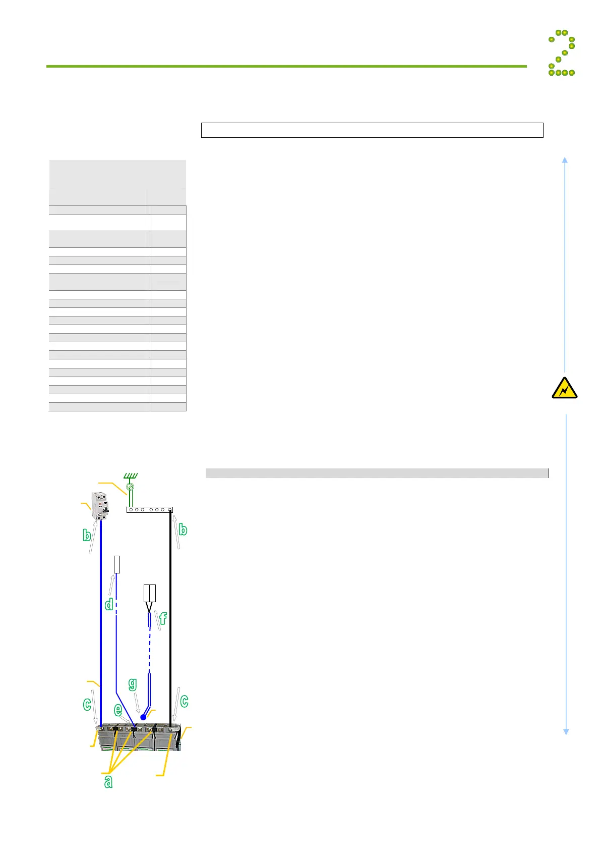
12 DC Connections Battery Cables
CAREFUL! Use correct polarity.
For 48V systems using the battery symmetry mid-point
measurement, refer to the figure in this page.
For other measurement methods and for 24V systems, refer to the
Battery Monitor’s user guide.
For each battery shelf:
(In cabinetized systems, steps b, d and f are usually performed in factory)
a Mount 3 intercell links to connect in series 4 battery blocks
b-c Connect battery cables to fuses and common DC rail, and to
the shelf’s outer terminals; (+) and (-)
d-e Connect battery symmetry cable, if applicable, to the input
terminal, and to the center terminal of the battery string
(+). Deviation from factory settings requires Symmetry
reconfiguration via PowerSuite
f-g Connect the temperature sensor cable, if applicable, to the
input terminals, and fix the temperature sensor (at the end
of the cable) to a suitable place in the middle of the
installed battery bank
Electric
Shock
General Torque
Recommended Ratings, FP2 Systems
Application,
Type & Size
Torque
(Nm)
Circuit Breakers
SIEMENS 18 mm,
5SX2, 5SX5 3.5
SIEMENS 27 mm,
5SX6, 5SX7, 5SP4
5.0
MG, C60 <=25A 3.5
MG, C60 >25A 3.5
CBI 13 mm, QY, QF, QA 3.0
Hex Nuts & Screws
(Knife Fuses, general)
M8.0 10.0
M10.0 16.0
M12.0 25.0
AC Terminal Blocks
1.5 mm
0.5
2.5 mm
0.5
4.0 mm
0.6
10 mm
2.0
16 mm
3.0
35 mm
4.0
70 mm
10.0
DC Rail Terminals
AKG 16 3.0
AKG 35 3.5
Note: General tolerance: ±10%.
NEC/CEC Requirements
(-48V) Oute
Terminal
+
0V Oute
Terminal
Link ”EG”
(DC Earth)
Common
DC Rail
EG
Battery
Fuse
Intercell Links
Battery
Cable
Chassis
Block1
- + + - + - + -
Block4Block3
Tem
. senso
Temp. Sensor cable 1
2-1
Smartpack
Basic
ntr
ll
r
X**
+
-
Symmetry 1.1
+
1
Battery Monitor
ID#<33>, Part
242100.300
Batter
Strin
1