Quick Start Guide Flatpack2 PS System, 4U, SP2-based 356825.103, 2v0 -2011-09
6
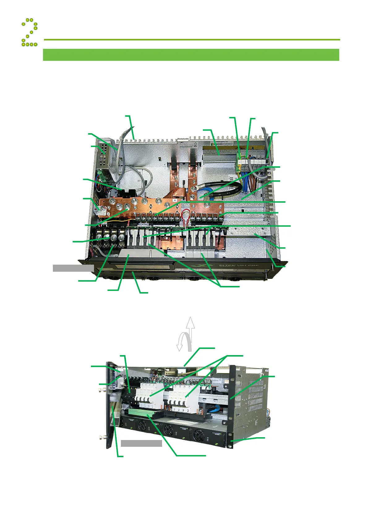
Location of Components, GA drawing
The pictures show an example of the location of components in Smartpack2-based Flatpack2 PS
Systems with 4U DC Distribution. Or refer to specific drawings included with your system.
The Smartpack2 Basic controller is located either inside the subassembly (picture below) or under
the top cover (see chapter on page 23).
Installation
AC Earth (PE)
connected to chassis
lternative stud for AC Earth
(PE) connection to chassis
C Mains Terminals (X:*)
Top view
LVBD Latching Contacto
rea for optional second LVLD
Latchin
Contacto
Common DC Output
Rail (+) Priority Load
Common DC Output
Rail (+) Non-Priority Load
rea “A” for mounting of
additional breakers or
SPD devices
rea for mounting I/O Monitor
units (when area “A” is not in
use)
DC Output (
)
F1
F2…
Common
Battery Rail (+)
Battery (
)
Fb1, Fb2…
I/O Monitor2 unit
(mounted underneath the controller)
Smartpack
Basi
Controlle
CAN Bus cable
Link “EG” Exchange Ground
connects DC Earth
TE
to chassis
Cable Fastening Plate
Battery Fuses
Load Fuses (MCBs)
LVLD latching contactor
underneath common rail
Area for mounting of additional
SPD devices
Smartpack
Master Controlle
I/O Monitor2 unit
(mounted underneath the controller)
Load Fuses (MCBs)
Smartpack
Maste
Controlle
Power shel
(1U high)
with 4 Flatpack2 Rectifiers (optional
several shelves)
Front view
Top Cove
Front door’s glass
DC Distribution (4U high)
with built-in Smartpack2 Master and
Basic controllers, I/O Monitor2
unit(s), load and battery fuses or
MCBs, etc.
SP2 Master Ethernet connecto
Battery Fuses