Quick Start Guide Flatpack2 PS System, 4U, SP2-based 356825.103, 2v0 -2011-09
7
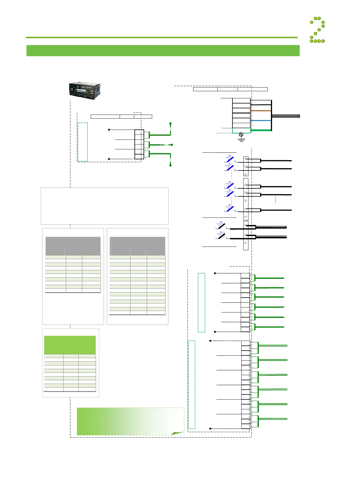
Connections, Factory Settings, etc
The schematic shows the connection terminals in Smartpack2-based Flatpack2 PS Systems with
4U DC Distribution. Or refer to specific drawings included with your system.
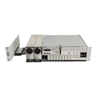
Installation
Flatpack
System, Integrated
4U DC Distr. with SP2 Ctrls
The figure shows the position of the relay contacts
when the PS system is in alarm mode of operation;
the relay coils are then de-energized (fail-safe
mode). The relay outputs are preprogrammed from
factory (Factory Settings).
Load Fuses
Common DC Output &
Battery Rails
Load Circuit 1
Load Circuit 3
Load Circuit 4
Load Circuit x
Load Circuit 2
Battery Cables, string 1
Battery
Fuses
16 mm
, 4
WG
max. wire section
(Only used in Flatpack2
systems with external battery
bank)
F3
F4
Fx
Battery Cables, string x
16 mm
, 4AWG
max. wire section
F2
F1
Fb2
Fb1
Input Circuit 1
Input Circuit 2
Input Circuit 3
Input Circuit 4
6
Config. Input
(From external equipment)
3
2
1
4
5
Config. Input
Config. Input
Config. Input
Config. Input
Config. Input
Input Circuit 5
Input Circuit 6
+
+
+
+
+
+
:***
Programmable Inputs
Max. 1.5 mm
,
(14
AWG) wire section
I/O Monitor2 CAN Node
Relay 1
Common Alarm
larm Circuit 1
larm Circuit 2
larm Circuit 3
larm Circuit 4
(To external equipment)
larm Circuit 5
larm Circuit 6
Alarm Relay Outputs
NO
NC
C
NO
C
NC
C
NO
NC
NO
C
NO
NC
C
NC
:****
NO
C
NC
Relay 2
Mains Alarm
Relay 3
Fuse Alarm
Load & Battery
Relay 4
High Battery Alarm
Relay 5
Low Battery Alarm
Relay 6
Rectifier Alarm
Max. 1.5 mm
,
14AWG
wire section
+
4
3
2
1
5
6
X:**
Configurable
Inputs
Temp Sense 1
+
Temp Sense 2
+
Temp Sense 3
Temperatu
e
Sensor 1
Temperatu
e
Sensor 2
Temperatu
e
Sensor 3
Smartpack
Basic controlle
FUNCTION SIGNAL PIN-OUT
(These multipurpose inputs may also be used as digital inputs,
e.g. for SPD monitoring)
(For Mains wiring reconfigu-
ration, see section
“Miscellaneous”)
FUNCTION SIGNAL TERM. POINT
:*
35 mm
, 1AWG,
max. wire section
4
3
2
1
PE
AC Mains Input
(Protective
Earth)
C Mains
Cable (Y)
7
6
5
PE
N
L1
L2
L3
For installations in USA and Canada only!
– The installation has to comply with the NEC/CEC requirements
– The distribution can only be used as a branch circuit distribution, if the circuit
breakers are UL489 (DITT) certified.
–For supply connectors, use wires suitable for at least 75˚C (167˚F), type: FEPW,
RH, RHW, THHW, THW, THWN, ZHHW, USE, ZX or similar. Use copper
conductors only
For installations
in USA and Canada only!
External DC Output Wires
Recommended Ratin
s
Current Wire Section
Max. (A) (mm
(AWG)
1 0.75 18
2 0.75 18
4 0.75 18
5 0.75 18
6 0.75 18
10 1.0 16
15 1.5 14
16 1.5 14
20 2.5 12
25 4 10
30 6 8
32 6 8
40 6 8
50 10 6
60 16 4
63 16 4
Recommendations if used as branch
circuits
For installations
in USA and Canada only!
External AC Output Wires
Recommended Ratin
s
Current Wire Section
Max. (A) (mm
(AWG)
6 0.75 18
10 1.0 16
13 1.5 14
16 1.5 14
20 4 10
25 6 8
32 6 8
40 10 6
50 16 4
63 25 3
Recommendations if used as branch
circuits. Based on 45˚C ambient
(factor 0.82)
For installations
outside USA and Canada!
External AC Input Wires
Recommended Ratin
s
Current Wire Section
Max. (A) (mm
(AWG)
6 0.75 18
10 1.00 16
13 1.25 16
16 1.50 14
25 2.50 12
32 4.00 10
40 6.00 8
63 10.00 6
80 16.00 4
100 25.00 2