Quick Start Guide Flatpack2 PS System, 4U, SP2-based 356825.103, 2v0 -2011-09
24
CAN Bus Nodes
The CAN Bus Nodes are control units connected to the power system’s CAN bus. They have a
rugged sealed-plastic design, with DIN-rail or Velcro tabs as standard mounting options.
When the CAN bus address is configured and the unit connected to the bus, it will automatically
communicate with the power system’s controller (“plug and play”). Configure then the CAN node
functionality using WebPower or PowerSuite.
Battery Monitor CAN Node
The Battery Monitor CAN Bus Node enables you to decentralize or increase the number of battery
symmetry measurements in your Compack-, Smartpack- or Smartpack2-based DC power supply
system. Also, it monitors the battery compartment temperature – using the built-in sensor – the
battery fuse – with a fuse monitoring input – and the battery current – via a current sense input.
Read also the “Installation Guide Battery Monitor CAN Node”, document 351507.033.
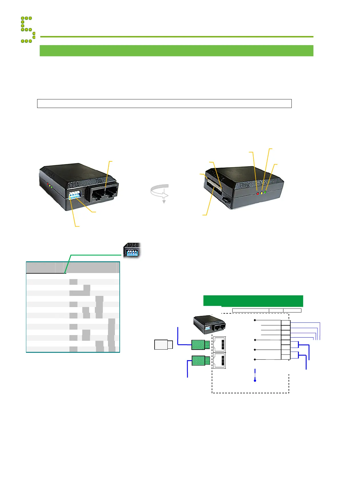
Appendix CAN Bus Nodes
CAN port 1&2
Electricall
identical
DIP switches
CAN ID address
DIP switch #1
Battery Monitor
Battery Monitor
Monitor Inputs
Terminal Block
Powe
LED Lamp
reen
Warning
LED Lamp
ellow
Pin 1
Pin 8
larm
LED Lamp
red
Batter
Monitor Connections
Part 242100.300
FUNCTION SIGNAL PIN-OUT
4
3
2
1
5
8
7
6
X:*
(From the
batteries)
Built-in Battery
Temperature Sensor
Battery
Monitor
From previous CAN
bus node
Batt. Symmetry 1
+
Batt. Fuse
CAN port 1&2
RJ45, 8 pins
+
+
+
+
Batt. Symmetry 2
Batt. Symmetry 3
Batt. Symmetry 4
+
Batt. Current
To next CAN bus
node
(From the current shunt)
(From the current shunt)
O
RJ45 CAN bus
termination plug,
if the Battery
Monitor is the
last node in the
CAN bus
1.5 mm
, 14
WG
max. wire section
Battery
Monitor
ID
#
DIP Switch Position
1
2
3
4
1
s
Monitor 33
OFF
OFF
OFF
OFF
2
nd
Monitor 34
ON
OFF
OFF
OFF
3
rd
Monitor 35
OFF
ON
OFF
OFF
4
th
Monitor 36
ON
ON
OFF
OFF
5
th
Monitor 37
OFF
OFF
ON
OFF
6th Monitor 38
ON
OFF
ON
OFF
7
th
Monitor 39
OFF
ON
ON
OFF
8
th
Monitor 40
ON
ON
ON
OFF
9
th
Monitor 41
OFF
OFF
OFF
ON
10
th
Monitor 42
ON
OFF
OFF
ON
11
th
Monitor 43
OFF
ON
OFF
ON
12
th
Monitor 44
ON
ON
OFF
ON
13
th
Monitor 45
OFF
OFF
ON
ON
14
th
Monitor 46
ON
OFF
ON
ON
Battery Monito
DIP switch configuration
ID <33>
(All switches OFF)
Note:
The
monitor’s
ID #
corresponds
to the DIP
switch’s
binary value
plus 33