Quick Start Guide Flatpack2 PS System, 4U, SP2-based 356825.103, 2v0 -2011-09
25
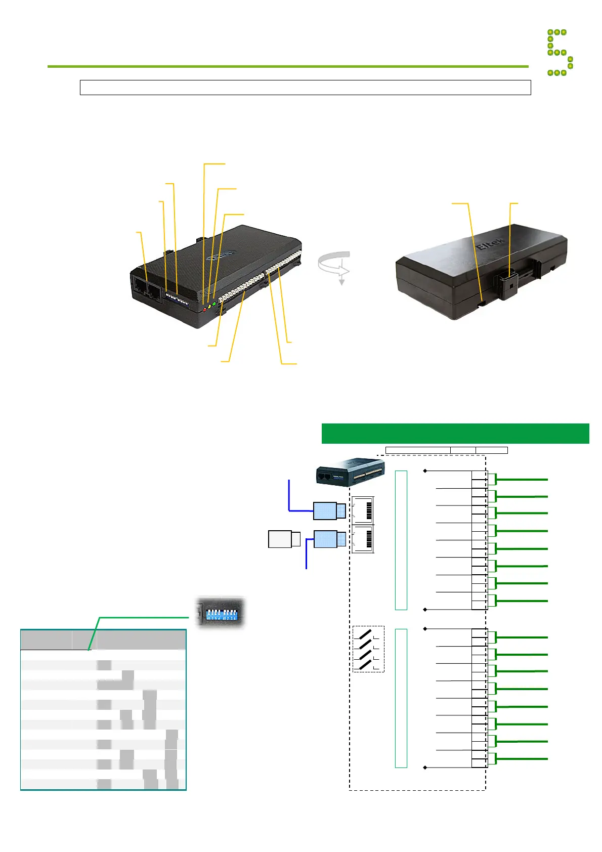
Load Monitor CAN Node
The Load Monitor CAN Bus Node enables you to decentralize and increase the number of input
fuse monitoring and current sense signals in your Compack-, Smartpack- or Smartpack2-based DC
power supply system. The fuse monitoring inputs are suitable for monitoring a wide range of
breakers in both positive and negative DC distributions.
Read also the “Installation Guide
Load Monitor CAN Node”,
document 351506.033.
CAN Bus Nodes Appendix
CAN port 1&2
Electricall
identical
DIP switches
CAN ID address
DIP switch #1
Load Monito
Powe
LED Lam
reen
Warning
LED Lamp
ellow
Alarm
LED Lam
red
Fuse Monitoring Inputs
Terminal Block X*
In
ut 1
Load Monito
DIN Rail
mounting
clips
Screw head
mounting slot (2x)
(Head’s diameter >5 mm
and <8 mm)
Current Sense Inputs
Terminal Block X**
Input 1
Load Monitor Connections
Voltage free relay outputs and Configurable monitoring inputs
FUNCTION SIGNAL PIN-OUT
Load Monito
To next
CAN bus node
CAN
port 1&2
RJ45, 8 pins
From previous
CAN bus node
O
RJ45 CAN bus termination plug, if the Load
Monitor is the last node in the CAN bus
(Customer Connections)
DIP
Switches
(5-8 always
OFF
1
2
3
4
Input Circuit 1
Input Circuit 2
Input Circuit 3
Input Circuit 4
6
Config. Input
(From breakers and external equipment)
3
2
1
4
5
Config. Input
Config. Input
Config. Input
Config. Input
Config. Input
Input Circuit 5
Input Circuit 6
Fuse Monitoring Inputs
+
+
+
+
+
+
X:*
+
+
8
Config. Input
7
Config. Input
Input Circuit 7
Input Circuit 8
Input Circuit 1
Input Circuit 2
Input Circuit 3
Input Circuit 4
6
Sense Input
(From current shunts)
3
2
1
4
5
Sense Input
Sense Input
Sense Input
Sense Input
Sense Input
Input Circuit 5
Input Circuit 6
Current Sense Inputs
+
+
+
+
+
+
X:**
+
+
8
Sense Input
7
Sense Input
Input Circuit 7
Input Circuit 8
1.5 mm
, 14
WG
max. wire section
Load
Monitor
ID
#
DIP Switch Position
1
2
3
4
1
s
Monitor 49
OFF
OFF
OFF
OFF
2
nd
Monitor 50
ON
OFF
OFF
OFF
3
rd
Monitor 51
OFF
ON
OFF
OFF
4
th
Monitor 52
ON
ON
OFF
OFF
5
th
Monitor 53
OFF
OFF
ON
OFF
6th Monitor 54
ON
OFF
ON
OFF
7
th
Monitor 55
OFF
ON
ON
OFF
8
th
Monitor 56
ON
ON
ON
OFF
9
th
Monitor 57
OFF
OFF
OFF
ON
10
th
Monitor 58
ON
OFF
OFF
ON
11
th
Monitor 59
OFF
ON
OFF
ON
12
th
Monitor 60
ON
ON
OFF
ON
13
th
Monitor 61
OFF
OFF
ON
ON
14
th
Monitor 62
ON
OFF
ON
ON
Load
onitor
DIP switch configuration
ID <49>
(All switches OFF)
Note:
DIP switch
positions 5
through 8 are
always to be OFF
The monitor’s
ID # corresponds
to the DIP
switch’s binary
value plus 49