Quick Start Guide Flatpack2 PS System, 4U, SP2-based 356825.103, 2v0 -2011-09
26
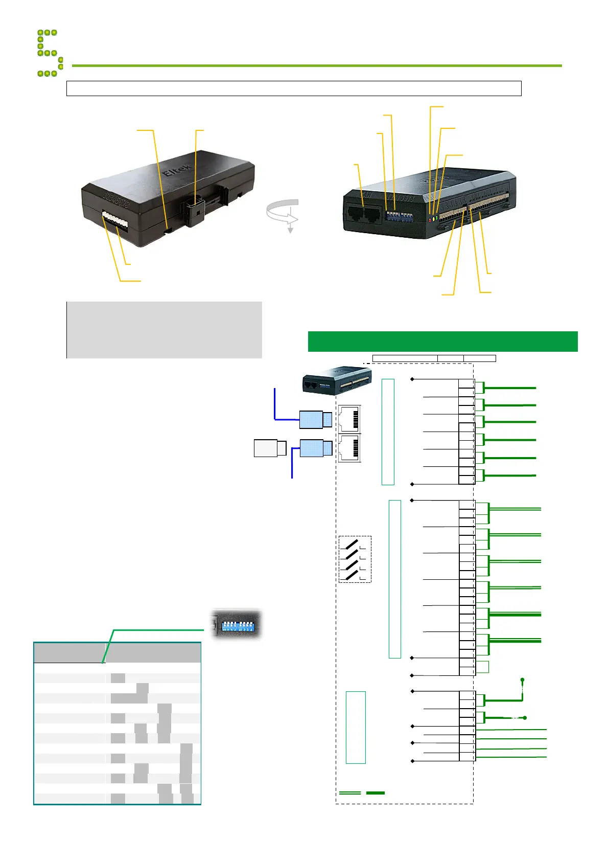
I/O Monitor and I/O Monitor2 CAN Nodes
Notice:
The figure shows the location of terminals and
LEDs in the I/O Monitor node.
The I/O Monitor2 node implements the same input
and outputs as the I/O Monitor node (X:*, X:**),
except for the Fan Control signals (X:***)
The I/O Monitor and the
I/O Monitor2 CAN Bus Nodes
enable you to decentralize and
increase the number of input
monitoring and output controlling
signals in your Compack-,
Smartpack- or Smartpack2-based
DC power supply system.
Also, the I/O Monitor node monitors
and controls the compartment
temperature inside fan-cooled
outdoor cabinets.
Read also the installation guides for
I/O Monitor CAN Node (document
351503.033) and for I/O Monitor2
CAN Node (document 351509.033).
Appendix CAN Bus Nodes
CAN port 1&2
Electricall
identical
DIP switches
CAN ID address
DIP switch #1
I/O Monito
Powe
LED Lam
reen
Warning
LED Lamp
ellow
Alarm
LED Lamp
red
Configurable Inputs
Terminal Block X*
Input 6
Relay Outputs
Terminal Block X**
Rela
1
I/O Monito
Fan Control Inputs & Outputs
Terminal Block X***
Pin 1
DIN Rail
mounting
clips
Screw head
mounting slot (2x)
(Head’s diameter >5 mm
and <8 mm)
I/O Monitor Connections
Voltage free relay outputs and Configurable monitoring inputs
FUNCTION SIGNAL PIN-OUT
I/O Monito
To next
CAN bus node
CAN
port 1&2
RJ45, 8 pins
From previous
CAN bus node
O
RJ45 CAN bus termination plug, if the I/O
Monitor is the last node in the CAN bus
(Customer Connections)
1.5 mm
, 14
WG
max. wire section
DIP
Switches
(5-8 always
OFF
1
2
3
4
Out In
(To and from
external fans
+
+
Temperature Sense 1
4
3
2
1
5
8
7
6
X:***
Temperature Sense 2
Temperatu
e
Sensor 1
Temperatu
e
Sensor 2
Tachometer In
ut 1
Tachometer Input 2
Fan Speed Monitor 1
Fan Speed Monitor 2
S
eed Control Out
ut 1
S
eed Control Out
ut 2
Fan Speed Control 1
Fan Speed Control 2
Fan Control
Inputs & Outputs
larm Circuit 1
larm Circuit 2
larm Circuit 3
larm Circuit 4
Relay 4
(To external equipment)
NO
NC
C
NO
C
NC
C
NO
NC
NO
C
NO
NC
C
NC
X:**
NO
C
NC
+
Relay 1
Relay 2
Relay 3
Relay 5
Relay 6
larm Circuit 5
larm Circuit 6
(To be shorted)
Not in use
Alarm Relay Outputs
Input Circuit 1
Input Circuit 2
Input Circuit 3
Input Circuit 4
6
Config. Input
(From external equipment)
3
2
1
4
5
Config. Input
Config. Input
Config. Input
Config. Input
Config. Input
Input Circuit 5
Input Circuit 6
+
+
+
+
+
+
X:*
Programmable Inputs
I/O
Monitor
ID
#
DIP Switch Position
1
2
3
4
1
s
Monitor 81
OFF
OFF
OFF
OFF
2
nd
Monitor 82
ON
OFF
OFF
OFF
3
rd
Monitor 83
OFF
ON
OFF
OFF
4
th
Monitor 84
ON
ON
OFF
OFF
5
th
Monitor 85
OFF
OFF
ON
OFF
6th Monitor 86
ON
OFF
ON
OFF
7
th
Monitor 87
OFF
ON
ON
OFF
8
th
Monitor 88
ON
ON
ON
OFF
9
th
Monitor 89
OFF
OFF
OFF
ON
10
th
Monitor 90
ON
OFF
OFF
ON
11
th
Monitor 91
OFF
ON
OFF
ON
12
th
Monitor 92
ON
ON
OFF
ON
13
th
Monitor 93
OFF
OFF
ON
ON
14
th
Monitor 94
ON
OFF
ON
ON
I/O
onitor
DIP switch configuration
ID <81>
(All switches OFF)
Note:
DIP switch
positions 5
through 8 are
always to be OFF
The monitor’s
ID # corresponds
to the DIP
switch’s binary
value plus 81