____________________________________________________________________________________
____________________________________________________________________________________
NTU Optical Network Terminals 15
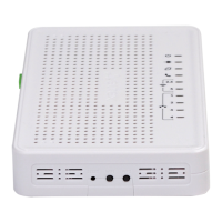
Fig. 6—NTU-2VC Rear Panel layout
Table 5—Description of the LEDs and controls located on the rear panel
a functional key that reboots the device and resets it to factory settings
TV set connector for CaTV
LAN 10/100/1000 1
LAN 10/100/1000 2
2 RJ-45 ports for connection to network devices
RJ-11 port to connect network devices
SC port (socket) for PON with GPON interface
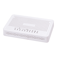
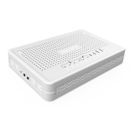
Fig. 7 shows a NTU-2V side and front panels.
Fig. 7—NTU-2VC Top Panel
The controls and LED indicators located on the NTU-2V side and top panels are shown in the table 6.