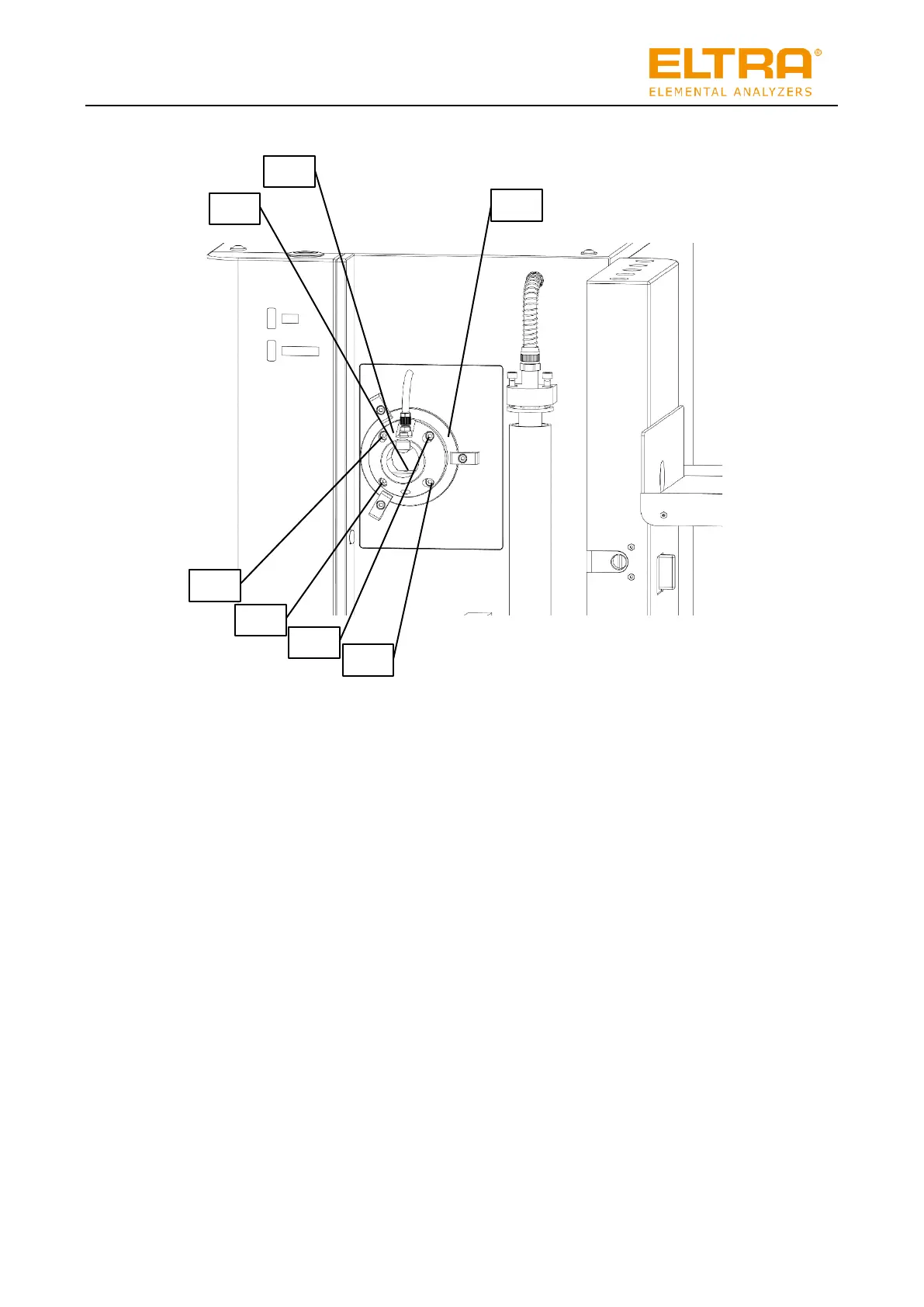
Fig. 39: Front of the HTFr with fitted furnace locking device
6. Using screws (9) to (12), secure the front furnace locking device (14) on the adapter ring
(8).
7. Turn the furnace locking device (14) and adapter ring (8) so that the support plate (13) is
aligned horizontally.
8. Gradually tighten each of the screws (9) to (12) in turn to ensure that the furnace locking
device does not get twisted. When tightening the screws, the O-ring is squeezed and the
tube pushed slightly backwards. The furnace locking device (14) and adapter ring (8)
should be aligned parallel to each other at all times.
9. Tighten the screws (2) to (4) so that the adapter ring (8) can no longer be moved.
The combustion tube has been inserted.