I
3
Fig. 4
Fig. A
Fig. B
Fig. C
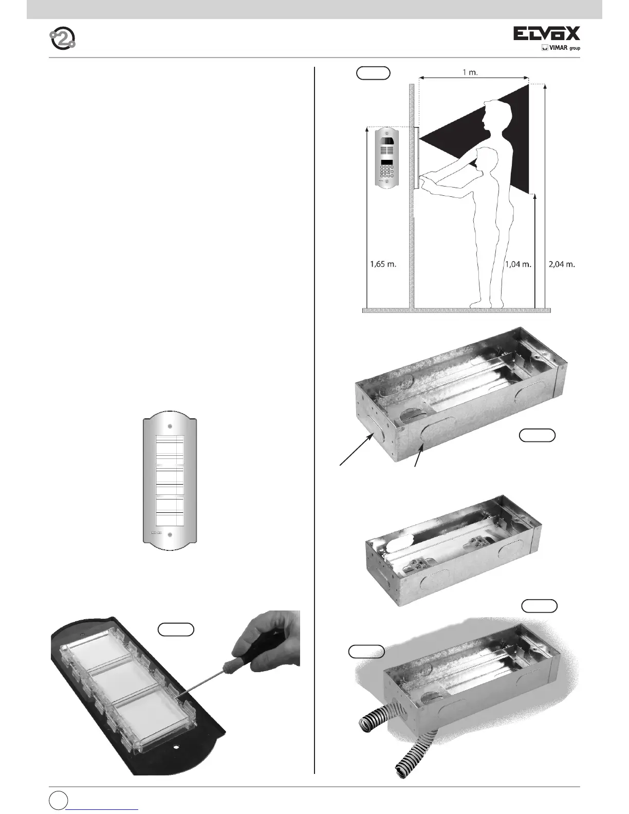
Points to be chosen for the cable to get through. To remove
with a screwdriver.
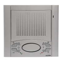
To reach the name-tags operate on the additional panel rear side
as indicated in figure.
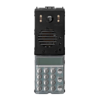
ART. 805N/T
Fig. 3
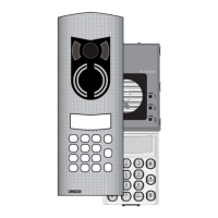
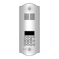
ADDITIONAL ENTRANCE PANELS
It possible to place side by side of the electronic basic entrance
panels one or more additional entrance panels and precisely type
805N/T for the basic entrance panels type 89F4/T, 89F7/T,
89F7/CT.
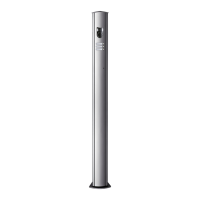
INSTALLATION OF THE ENTRANCE PANEL
The installation of the basic entrance panel requires the use of
the flush-mounted back box placed inside the package.
Installation
- Install the back boxes at approx. 1,65 m high from the back
box upper side to the soil (Fig. 4).
- Fit the back box inside the wall making the tubes for the cable
pass through the holes, see sequence Fig. A, Fig. B, Fig. C.
- If the installation requires the coupling of more back boxes,
use the proper separator brackets to fix the boxes among
them (Fig. 5).
- Connect the terminal block of the electronic unit to the termi-
nal block by means of the cabling present on the upper side
(Fig. 6).
- Insert the microphone in proper seat placed on the rear side of
the brass entrance panel (Fig. 7).
- Close the entrance panel paying attention that the electronic of
same adheres perfectly to the brass plate allowing the push-
buttons to be activated until the run end. Should this not be
possible, adjust the screw inside the flush-mounted back box,
thus allowing the electronic unit to adhere to the brass plate
(Fig. 8).
- Close the entrance panel by using the proper door lock blocks
(Fig. 9)
- Carry out the programming phases.
 Loading...