Interpreting LED activity
39
Operating the DS-5300B
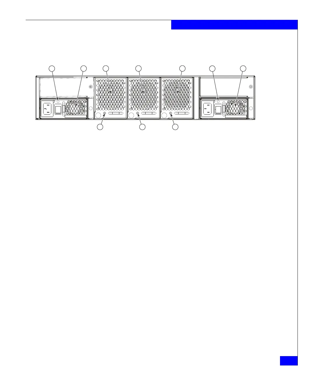
Figure 4 LEDs on non-port side of the DS-5300B
Table 2 on page 40 describes the LEDs on the nonport side of the
switch.
1 Power Supply #2 Status LED 6 Power Supply #1 Status LED
2 Power Supply #2 7 Power Supply #1
3Fan Assembly #3 8Fan Assembly #3 Status LED
4Fan Assembly #2 9Fan Assembly #2 Status LED
5 Fan Assembly #1 10 Fan Assembly #1 Status LED